
Method of making a filter cartridge that uses thermoforming step

a technology of thermoforming step and filter cartridge, which is applied in the direction of colloidal chemistry, manufacturing tools, separation processes, etc., can solve the problems of increasing pressure drop therethrough, introducing complexity as well as weight, bulk and cost, and reducing the utilization of filter media, etc., to achieve easy and inexpensive manufacturing, low cost, and low manufacturing steps

Inactive Publication Date: 2005-07-28
3M INNOVATIVE PROPERTIES CO
View PDF54 Cites 23 Cited by
  • Summary
  • Abstract
  • Description
  • Claims
  • Application Information

AI Technical Summary

Benefits of technology

[0012] The present invention also provides a method of making a filter element, which in brief summary comprises the steps of: (i) providing a mass of filter material; (ii) providing a thermo-formable sheet material; and (iii) thermo-forming the sheet material around at least part of the mass of filter material to encapsulate the filter material and prevent the passage of fluid between the filter and sheet materials, thus preventing the passage of fluid through the filter element other than along a filtering path through the filter material.
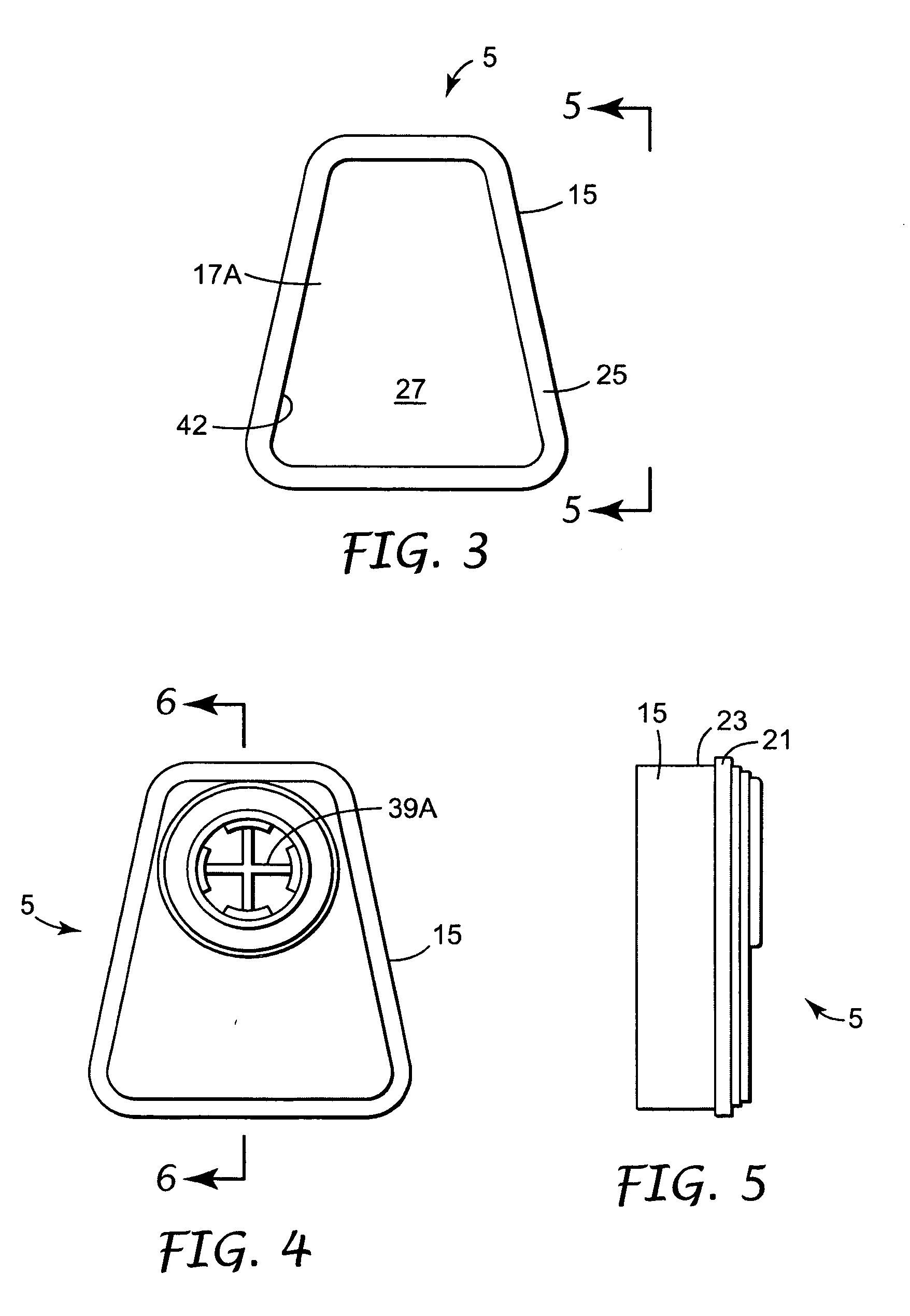
[0013] Relative to the filter elements and cartridges that have been known in the art, the present invention can allow filter elements, such as filter cartridges for respirators, to be manufactured using relatively few components. Further, such filter elements can be made using relatively few manufacturing steps. A housing, into which a mass of filter material may be contained, can be produced through a thermo-forming step that enables a wall of the housing to contact the filter material to prevent passage of fluid between the filter material and the housing sidewall. The housing, thus, can be easily and inexpensively manufactured while providing a sealing means for ensuring—when the filter element is used in a respirator—that essentially all inhaled air passes through the filter element. The thermo-formed sheet material also may act as a retaining means for securing the mass of filter material to the housing. These features can enable a filter cartridge to be produced for a respirator, which cartridge is relatively light in weight, possesses minimal parts, and is relatively easy to manufacture.

Problems solved by technology

The necessity for this number of parts and processing steps introduces complexity as well as weight, bulk, and cost.
A further problem is experienced when a packed bed respirator is combined in series with a particulate filter for use in environments containing particulates as well as vapor hazards such as in paint spray applications.
In this situation, the retaining grids and screens may create nonuniform airflow pathways within the particulate filter, resulting in reduced utilization of the filter media and increased pressure drop therethrough.
Loaded structures generally suffer from having a lower sorbent particle density than the packed beds.

Method used


Image

  • Method of making a filter cartridge that uses thermoforming step
  • Method of making a filter cartridge that uses thermoforming step
  • Method of making a filter cartridge that uses thermoforming step

Examples


Embodiment Construction

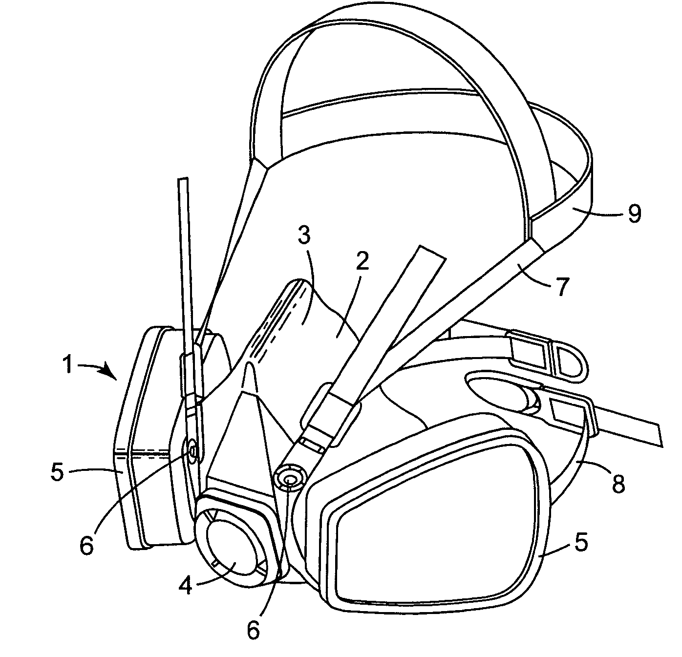
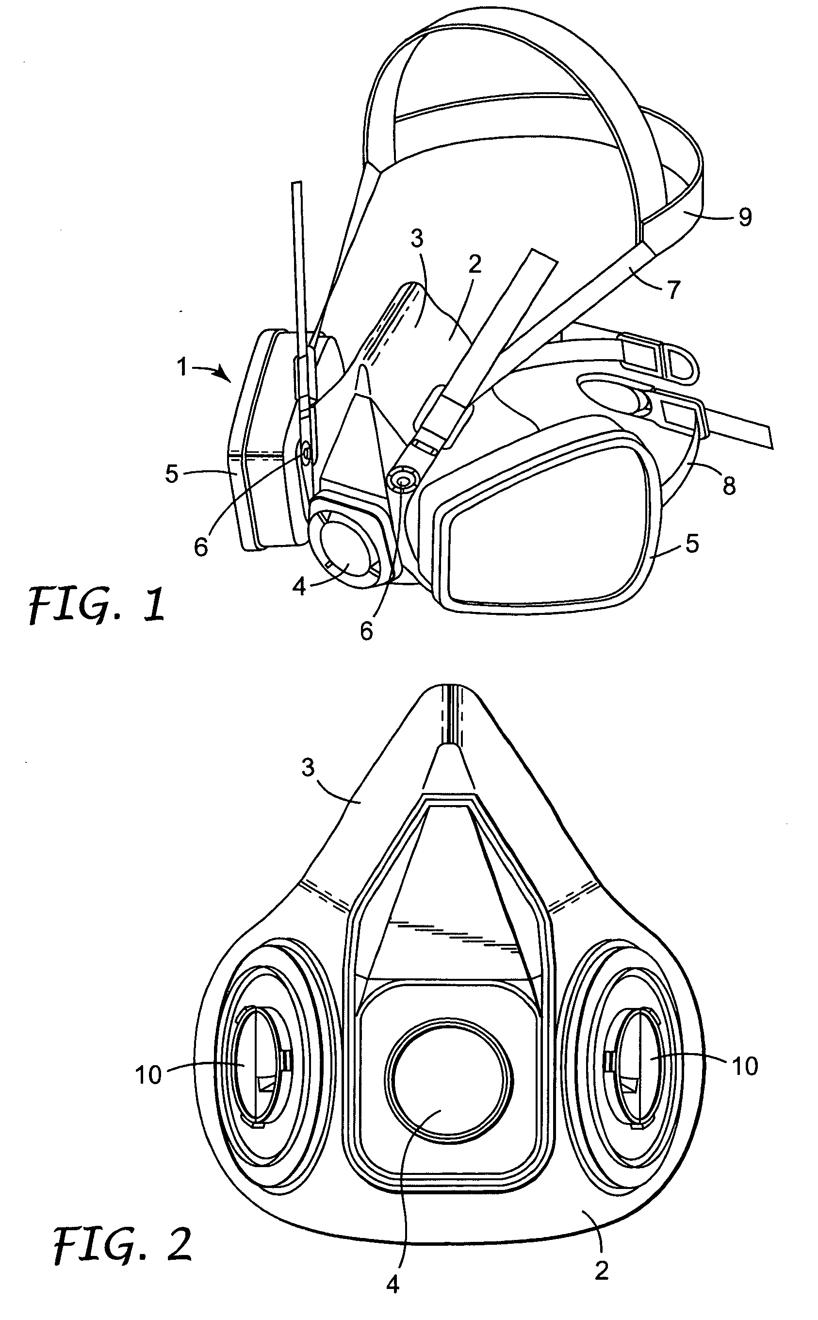
[0031]FIGS. 1 and 2 show one form of a respiratory half-mask that is intended to fit over the nose, mouth, and chin of the wearer. The mask 1 comprises a face-piece 2 that may be produced by being injection molded from a soft, compliant material (for example, a rubber material) and that has an inturned cuff (not visible in the drawings) around its edge. When the mask is worn, the cuff forms a seal against the wearer's skin. The face piece 2 defines an interior gas space that is located between the wearer's face and the face piece 2 when the mask 1 is being worn. The face-piece 2 has a central portion 3, intended to extend over the bridge of the wearer's nose, in which is mounted an exhalation valve 4. On opposing sides of the exhalation valve 4, the face-piece supports inhalation valves (not visible) over which filter cartridges 5 are mounted filter cartridges 5. At the sides of the face-piece are attachments 6 for upper and lower headbands 7, 8 (only those for the upper headband be...


PUM

PropertyMeasurementUnit
massaaaaaaaaaa
compressive forcesaaaaaaaaaa
thicknessaaaaaaaaaa

Abstract

Method for making a filter cartridge that is suitable for attachment to a respiratory mask. The method comprises the steps of (a) providing a mass of filter material; (b) providing a filter cartridge housing that has an inlet and outlet and a sidewall that includes sheet material; and (c) thermoforming the sheet material of the housing sidewall around at least part of the mass of filter material to place the housing sidewall in direct contact with the mass of filter material to encapsulate the filter material so that fluid is prevented from passing through the filter cartridge from the inlet to the outlet without being filtered by the mass of filter material.

Description

[0001] This application is a divisional of U.S. Ser. No. 10 / 252,623, filed Sep. 23, 2002, now allowed, the disclosure of which is herein incorporated by reference.[0002] The present invention relates to a method of making a filter cartridge that is suitable for use, for example, in a respirator, an air filtration unit, and other filtering apparatus. BACKGROUND [0003] A filter element often needs to be replaceable so that when it reaches the end of its useful life, it can be removed from the filtering apparatus in which it is used and can be replaced by a new filter element. Filter elements are commonly in the form of a cartridge, the housing of which may be provided with some form of attachment mechanism that enables the cartridge to be fitted in, and removed from, the filtering apparatus in which it is used. In other cases—for example, certain types of respiratory masks—the filtering apparatus is intended to be discarded when the filter element reaches the end of its useful life, a...

Claims


Application Information

Patent Timeline
Patent Type & Authority Applications(United States)
IPC IPC(8): A62B23/02B01D46/52
CPCA62B23/02B01D46/521Y10S55/33Y10S55/35B01D2271/02A62B18/02B01D46/52
Inventor VINER, ANDREW S.CONLAN, AUDRA A.CORMACK, BRIANWATSON, MALCOLM R.HENDERSON, CHRISTOPHER P.CURRAN, DESMOND T.WILLIAMS, ELFED I.
Owner 3M INNOVATIVE PROPERTIES CO
Learn More