Silencer and electronic equipment

a technology of electronic equipment and fan noise, which is applied in the direction of mechanical equipment, engine components, machines/engines, etc., can solve the problems of increased fan noise, increased product cost, and increased fan noise, and achieve the effect of reducing fan nois

Inactive Publication Date: 2005-07-28
FUJITSU LTD
View PDF31 Cites 75 Cited by
  • Summary
  • Abstract
  • Description
  • Claims
  • Application Information

AI Technical Summary

Benefits of technology

[0028] It is a general object of the present invention to provide a technology for silencing fan noise that

Problems solved by technology

However, with the method of cooling using the fan, there is a problem such that increasing the number of rotations of the fan in order to increase the cooling efficiency results in increased fan noise.
Moreover, while only a small-sized fan can be fit into the downsized electronic equipment as described above, it is known that with the same air amount, the smaller the fan the larger the fan noise.
However, with the water-cooling, the structure of the apparatus becomes complicated so as to cause an increased product cost, and the enlarged apparatus runs counter to the demand for downsizing.
Moreover, a problem arises such that an increased number of components leads to an increased failure rate, so as to cause decreased reliability of the electronic equipment into which the water-cooled cooling apparatus is fit.
Moreover, when the CPU continues to operate for more than or equal to a certain time period, there is a case such that the number of rotations of the fan becomes

Method used


Image

  • Silencer and electronic equipment
  • Silencer and electronic equipment
  • Silencer and electronic equipment

Examples


first embodiment

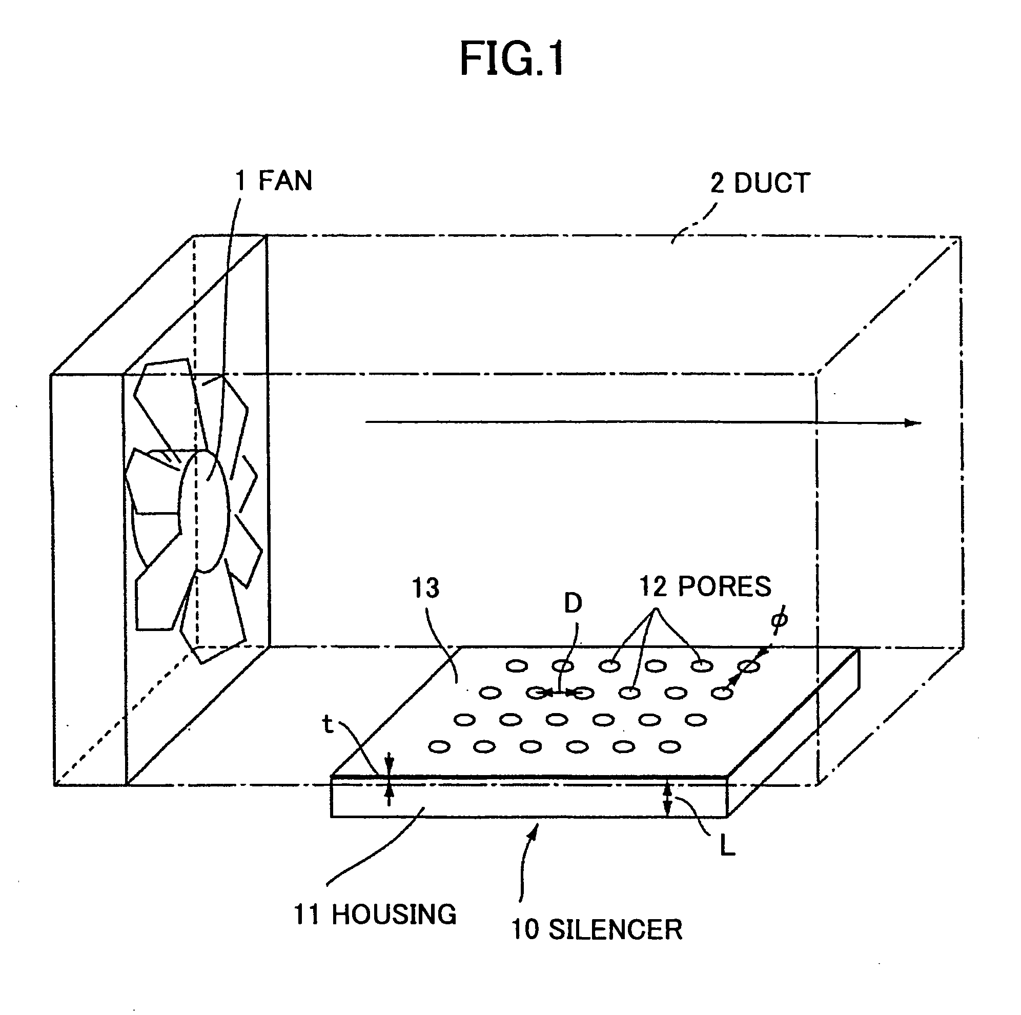
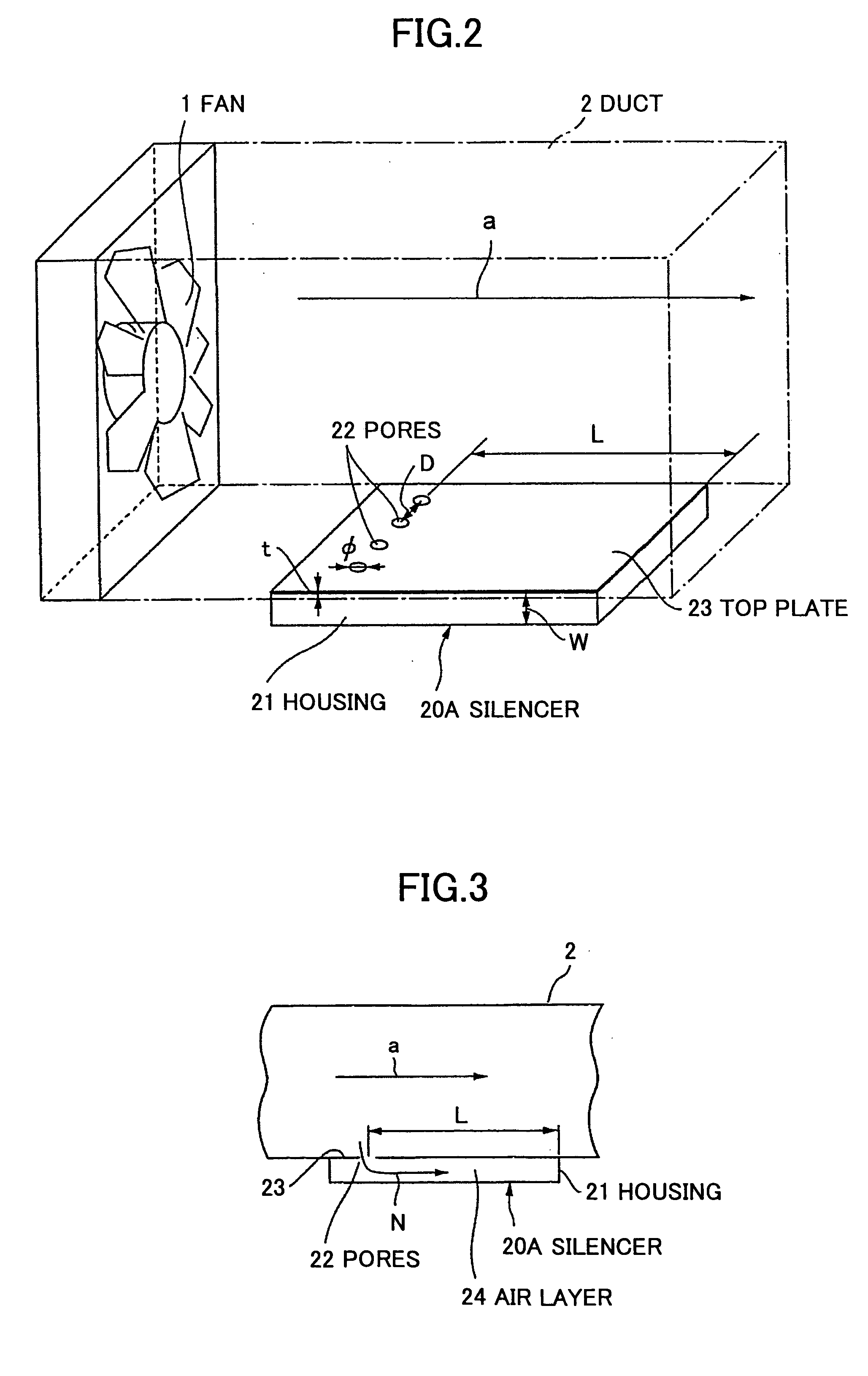
[0076]FIGS. 2 and 3 illustrate a silencer 20A being the present invention. It is noted that the same elements in FIGS. 2, 3, and each of the subsequent figures used in describing each embodiment as the elements illustrated in FIG. 1 have applied the same letters.

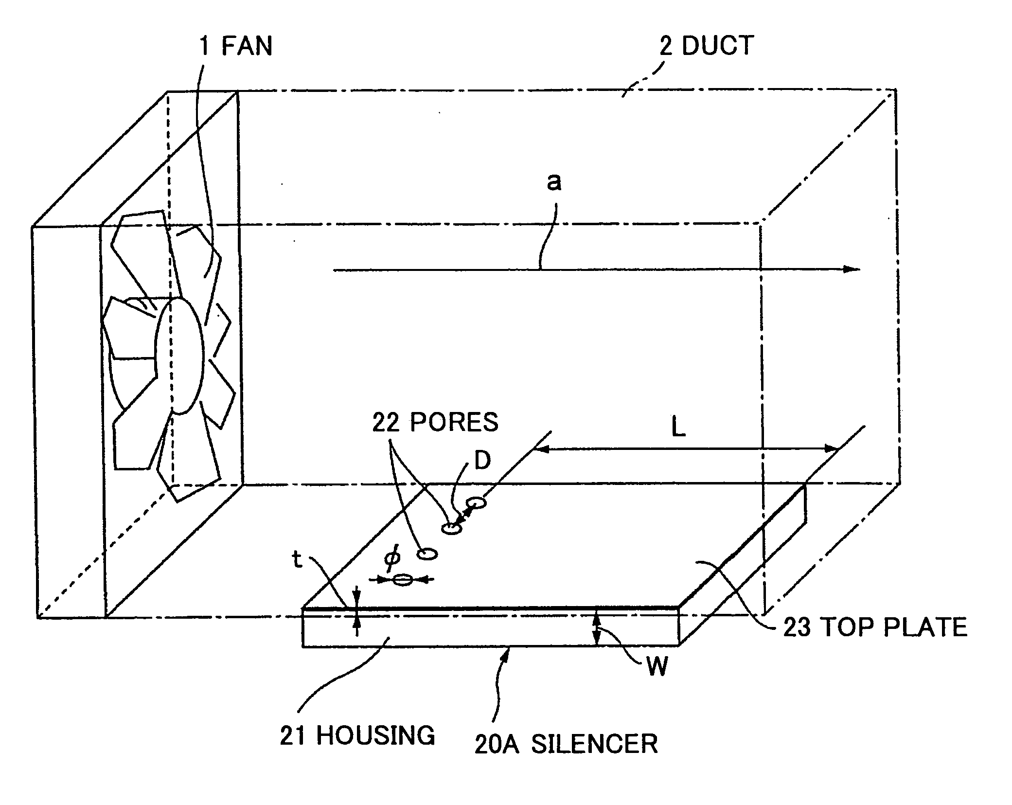
[0077] The silencer 20A in the present embodiment is configured from a housing 21 and pores 22 being formed at a top plate 23 of this housing 21. The housing 21 has a flat enclosing shape and is configured to be enclosed except for the pores 22. Therefore, a space (below referred to this space as an air layer 24) is formed within the housing 21. This housing 21 is set up at a duct 2 of a fan 1 generating cooling air.

[0078] The fan 1 and the duct 2 are set up within an apparatus mainframe 72 of electronic equipment 70 such as a desktop PC as illustrated in FIG. 38 so that materials to be cooled such as a CPU, etc., are cooled by cooling air generated at the fan 1. It is noted that applying the present invention is not to be ...

second embodiment

[0090] Next, the present invention is described.

[0091]FIGS. 6 and 7 illustrate a silencer 20B being the second embodiment. The silencer 20B in the present embodiment is characterized in that a partition plate 25 is provided within the housing 21 in the silencer 20A in the first embodiment. It is noted that in each of the diagrams for use in describing the second and the subsequent embodiments, the same elements as the elements illustrated in FIGS. 1 and 2 have applied the same letters so as to omit the explanations for the elements.

[0092] This partition plate 25 is being set up so as to be roughly parallel to the direction “a” of flow of the cooling air generated at a fan 1 and also to be roughly parallel to a top plate 23. Also, the partition plate 25 has the edge of the side which is upstream relative to the direction of the flow of the cooling air (the left-hand side in FIG. 7) fixed to the inner wall of the housing 21.

[0093] By configuring as described above, an air layer 24 f...

third embodiment

[0096] Next, the present invention is described.

[0097]FIG. 8 illustrates a silencer 20C being the third embodiment. The silencer 20C in the present embodiment is characterized in that sound-reflecting plates 28 are provided at the upper passage 26 and the lower passage 27 that are divided by the partition plate 25 in the silencer 20B being the second embodiment.

[0098] These sound-reflecting plates 28, being provided at the position at which the sound wave to be noise that is introduced from a pore 22 is reflected within a housing 21, perform a function of guiding at this reflecting position the direction of the reflecting to the direction to which each of the passages 26 and 27 extends. Therefore, each of the sound-reflecting plates 28 is set up so as to have approximately a 45-degree angle relative to a top plate 23 and the partition plate 25.

[0099] Thus, having provided within the housing 21 the sound-reflecting plates 28 for guiding the sound wave to be noise enables efficient ...


PUM


Abstract

A silencer is disclosed that includes a housing having a flat enclosing shape and having formed therein a passage for silencing; and pores, being formed at the housing so as to be communicatively connected with the passage, into which a sound wave to be noise is introduced. The pores, being formed close to the periphery of the housing, are configured so that the sound wave travels in the planar direction of the housing.

Description

CROSS-REFERENCE TO RELATED APPLICATION [0001] This application is a U.S. continuation application filed under 35 USC 111(a) claiming benefit under 35 USC 120 and 365(c) of PCT application JP02 / 13679, filed Dec. 26, 2002, which is hereby incorporated by reference.BACKGROUND OF THE INVENTION [0002] 1. Field of the Invention [0003] The present invention generally relates to a technology for silencing fan noise, and particularly relates to a silencer suitable for use in a fan-noise silencing process and electronic equipment having provided therein the silencer. [0004] 2. Description of the Related Art [0005] In recent years and continuing, as small-sized electronic equipment such as a notebook PC and a desk-top PC is made smaller and faster, the amount of heat dissipation required for a semiconductor apparatus (such as a CPU) set up inside is on the increase. It is possible to air-cool using a fan as means for cooling the semiconductor apparatus. [0006] However, with the method of cooli...

Claims


Application Information

Patent Timeline
IPC IPC(8): F01N1/00F01N1/02
CPCF01N1/023F01N1/003
Inventor FURUYA, HIROYUKI
Owner FUJITSU LTD
Why Eureka
Try Eureka