Aeration and mixing trough

a technology of aeration system and mixing trough, which is applied in the direction of moving filter element filter, separation process, filtration separation, etc., can solve the problems of pollution, direct threat to the water used for human consumption, and myriad of environmental problems, so as to improve aeration

Inactive Publication Date: 2005-07-28
CHEMSTREAM
View PDF10 Cites 0 Cited by
  • Summary
  • Abstract
  • Description
  • Claims
  • Application Information

AI Technical Summary

Benefits of technology

[0010] The present, invention is an improvement to existing aeration technology wherein contaminated water is chemically treated and aerated while being gravity-fed through a trough. A series of slats is positioned in the trough to interrupt the flow and induce mixing and aeration. The improvement includes an array of aeration edges removably installed over the slats. Also included is a holder for containing chemical treatment matter therein. The aeration edges consist of upper and lower plates stacked one on top of the other. Each plate is provided with horizontal fingers extending in a direction downstream relative to the flow direction of the treated water. Each finger terminates in a baffle, which baffle is positioned substantially perpendicular to its finger. The fingers of the lower plate are vertically spaced from and extend further upstream than the fingers of the upper plate. The aeration edge assembly greatly enhances aeration and permits the chemical treatment to be more thoroughly mixed with the water. This allows additional precipitation of heavy metals from the water prior to their theoretical precipitation pH point. The aeration edges are sized to fit 4′, 2′ and 1′ troughs. The chemical matter holder is designed to house a conventional chemical gel log.

Problems solved by technology

Contaminated water has caused a myriad of environmental problems in the past four decades.
This scenario threatens the fish and wildlife that depend on the rivers and streams for sustenance.
Such contamination is also a direct threat to the water used for human consumption.
The apparatus appears to be difficult to clean and / or repair because of the arrangement of the plural stages.
The coiled surfaces are enclosed in a chamber making cleaning and repairing difficult.

Method used


Image

  • Aeration and mixing trough
  • Aeration and mixing trough
  • Aeration and mixing trough

Examples


Embodiment Construction

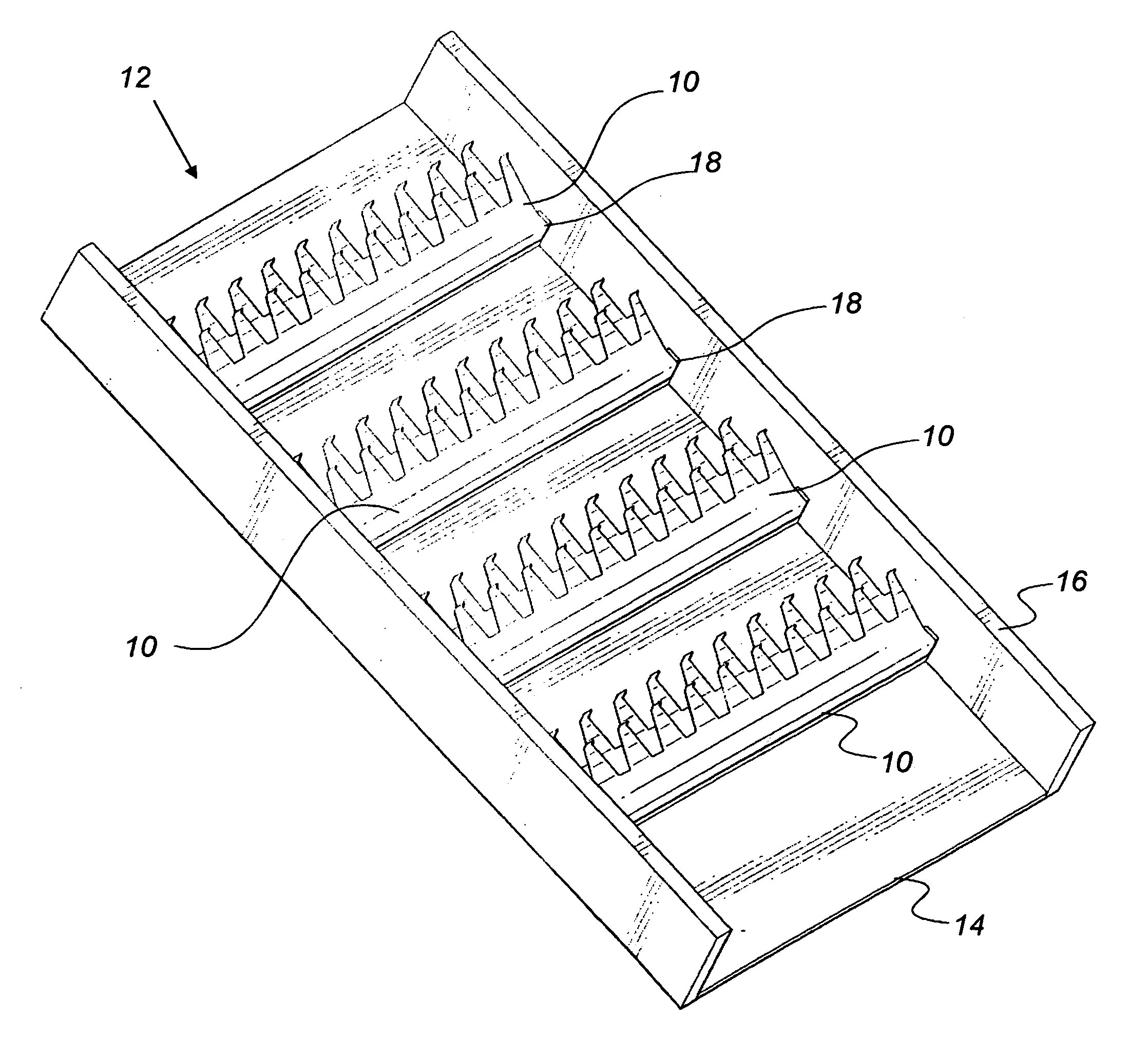
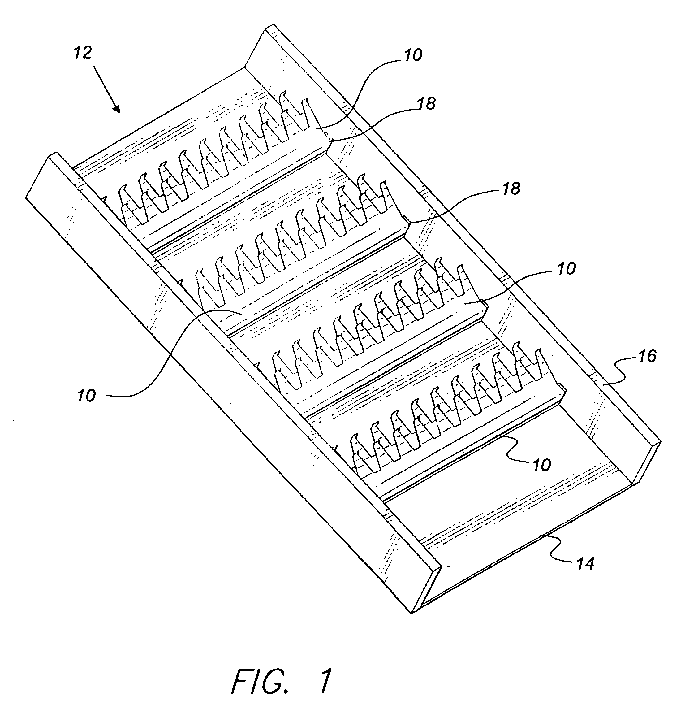
[0021] Attention is first directed to FIG. 1 wherein an array of aeration edge units 10 is mounted in a trough 12. Trough 12 comprises a bottom 14 fabricated from marine grade plywood, HDPE or stainless steel. Side panels 16 and slats 18 are fabricated from pressure treated yellow pine, HDPE or stainless steel. The trough is sealed with waterproof silicone. An inset fastening system (not shown) may be provided to secure the trough at an incline. As best seen in FIGS. 2 and 3 an aeration edge unit comprises a bottom plate 20 having a U-shaped end 21 and having plural co-planar fingers 20a extending therefrom. Fingers 20a terminate in respective baffle members 20b. An upper plate 22 having an L-shaped end 23 rests atop plate 20. Plate 22 is also provided with plural co-planar fingers 22a extending therefrom. Fingers 22a are vertically spaced from fingers 20a and are horizontally offset therefrom. Fingers 22a terminate in respective baffle portions 22b. As shown in FIG. 3, plates 20 an...


PUM

PropertyMeasurementUnit
activating wavelengthaaaaaaaaaa
pHaaaaaaaaaa
chemicalaaaaaaaaaa

Abstract

Contaminated water is chemically treated and aerated while being gravity fed through a trough. A series of slats are positioned in the trough to interrupt the flow and induce mixing and aeration. An array of aeration edges is removably installed over the slats. A holder for containing chemical treatment matter therein is positioned adjacent each slat. The aeration edges consist of upper and lower plates stacked one on top of the other. Each plate is provided with horizontally fingers extending in a direction downstream relative to the flow direction of the treated water. Each finger terminates in a baffle, which baffle is positioned substantially perpendicular to its finger.

Description

BACKGROUND OF THE INVENTION [0001] 1. Field of the Invention [0002] The present invention generally relates to purification systems. More specifically, the present invention is drawn to an aeration system for enhancing oxygenation and metal ion precipitation in water purification systems. [0003] 2. Description of the Related Art [0004] Contaminated water has caused a myriad of environmental problems in the past four decades. Many manufacturing techniques use water to flush away contaminates, which contaminates can end up in our rivers and streams. This scenario threatens the fish and wildlife that depend on the rivers and streams for sustenance. Such contamination is also a direct threat to the water used for human consumption. Most forward-thinking governments are now committed to improving the quality of the earth's water supply. To this end, inventions have been devised to improve water purification systems. Examples of these inventions are exemplified in U.S. Pat. No. 2,673,451 ...

Claims


Application Information

Patent Timeline
Patent Type & Authority Applications(United States)
IPC IPC(8): C02F1/52C02F1/64C02F1/74
CPCC02F1/645C02F2101/20C02F1/74
Inventor KAUFMAN, MICHAEL J.
Owner CHEMSTREAM
Why Eureka
Try Eureka