Image-recording apparatus and image-recording process

a technology of image recording and recording apparatus, which is applied in the direction of photomechanical equipment, circuit masks, instruments, etc., can solve the problems of progressively becoming finer, recording positions being offset, and substrate cavity alignmen

Inactive Publication Date: 2005-07-28
FUJIFILM HLDG CORP +1
View PDF6 Cites 19 Cited by
  • Summary
  • Abstract
  • Description
  • Claims
  • Application Information

AI Technical Summary

Benefits of technology

[0013] The present invention has been devised in order to eliminate the problems described above, and an object of the present invention is to provide an image-recording apparatus and image-recording proces

Problems solved by technology

However, patterns recorded on PWBs (wiring patterns) are progressively becoming finer in accordance with increases in density of mounting of components, and a problem has emerged with recording positions being offset due to expansion/contraction of substrates, which occurs in a pressing process which is usually performed in a heated state.
Thus, in a case of, for example, a multi-layer printed wiring board, alignment of cavities formed in the substrates, such as through-holes and the like, with the patterns of the respective layers cannot be performed with high accuracy.
Conseqently, there is a problem in that packing density of such PWBs cannot be raised.
With FPDs, substrate sizes are progressively becoming larger with a view to raising productivity, and a problem has emerged with picture positions being offset due to increases in expansion/contraction amounts of substrates through processes of heating.
For example, in a case in which a color filter pattern is reco

Method used


Image

  • Image-recording apparatus and image-recording process
  • Image-recording apparatus and image-recording process
  • Image-recording apparatus and image-recording process

Examples


first embodiment

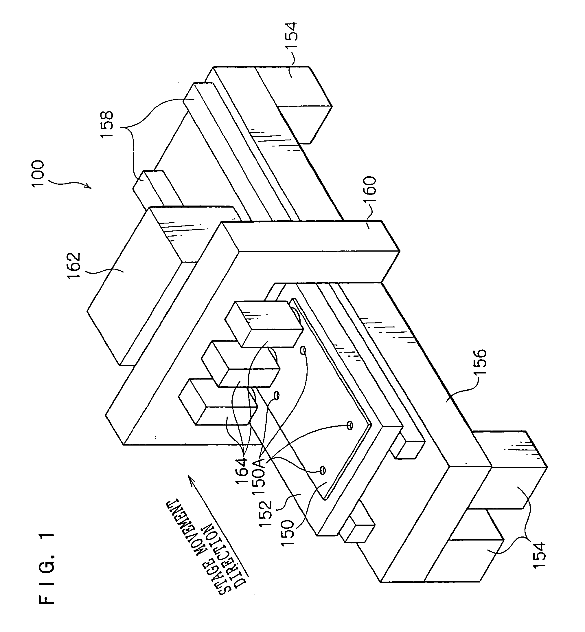
[0032]FIG. 1 shows a flathead-type image-recording apparatus 100 relating to a present embodiment.

[0033] The image-recording apparatus 100 is provided with a thick board-form setting pedestal 156, which is supported by four leg portions 154, and is provided with a flat board-form stage 152 with two guides 158, which extend in a stage movement direction, interposed between the setting pedestal 156 and the stage 152. The stage 152 is provided with a function for retaining a printed wiring board (PWB) 150 at a surface thereof by suction.

[0034] A longitudinal direction of the stage 152 is oriented in the stage movement direction, and the stage 152 is guided by the guides 158 and supported by the same so as to be reciprocally movable (scannable). At this image-recording apparatus 100, an unillustrated driving apparatus is provided for driving the stage 152 along the guides 158. The stage 152 is controlled for driving by a stage control section 112, which is described later (see FIG. 5)...

second embodiment

[0110] For this second embodiment, a variant example is described which is a case in which the present invention is applied, for a sequential production process which successively produces a plurality of PWBs (herein, a process of production of one lot of PWBs), to a case in which variation data is acquired from an initial predetermined number of the PWBs and this variation data is used for producing the rest of the PWBs. Note that structure of an image-recording apparatus relating to this second embodiment is the same as the image-recording apparatus 100 relating to the first embodiment (see FIGS. 1 to 5), and descriptions thereof are not given here.

[0111] Herebelow, operations at a time of production of one lot of the PWBs 150 at the image-recording apparatus 100 relating to this second embodiment will be described in detail with reference to FIGS. 5 and 12. FIG. 12 is a flowchart showing a processing flow at the time of production of one lot of the PWBs 150 at the image-recordin...


PUM

PropertyMeasurementUnit
Timeaaaaaaaaaa
Deformation enthalpyaaaaaaaaaa

Abstract

An image-recording apparatus and image-recording process capable of suppressing mispositioning of recording of an image from an ideal position while correcting for mispositioning of the recording of the image in a case in which a recording medium is deformed to an arbitrary shape. When a wiring pattern is to be recorded on a PWB (printed wiring board) using raster data, deformation information representing a state of deformation of the PWB is acquired beforehand. On the basis of this deformation information, the raster data is converted such that the wiring pattern that is recorded will, after the deformation, have the same shape as the wiring pattern represented by the unconverted raster data. On the basis of the converted raster data, the wiring pattern is recorded at the PWB before the deformation.

Description

CROSS-REFERENCE TO RELATED APPLICATION [0001] This application claims priority under 35 USC 119 from Japanese Patent Application No. 2003-369244, the disclosure of which is incorporated by reference herein. BACKGROUND OF THE INVENTION [0002] 1. Field of the Invention [0003] The present invention relates to an image-recording apparatus and an image-recording process, and more particularly relates to an image-recording apparatus and image-recording process for deforming an image represented by image information, in accordance with deformation of a recording medium on which the image is to be recorded, and recording the image on the recording medium. [0004] 2. Description of the Related Art [0005] Laser-scanning image-recording devices which are capable of recording patterns directly on substrates are known as devices for recording predetermined patterns on substrates such as printed wiring boards (hereinafter referred to as PWBs), flat panel displays (hereinafter referred to as FPDs) ...

Claims


Application Information

Patent Timeline
IPC IPC(8): G03F7/20H01B13/00H05K1/02H05K3/00H05K3/06H05K3/46
CPCG03F7/2057G03F9/7003H05K1/0269H05K3/0082H05K2203/163H05K3/4652H05K3/4679H05K2201/09918H05K3/064G03F7/20
Inventor OZAKI, YUKIHIROSUGANUMA, ATSUSHIMORITA, SEIKI
Owner FUJIFILM HLDG CORP
Why Eureka
Try Eureka