Method of manufacturing refiner elements

Inactive Publication Date: 2005-07-28
THEUT PATRICK J
View PDF16 Cites 32 Cited by
  • Summary
  • Abstract
  • Description
  • Claims
  • Application Information

AI Technical Summary

Benefits of technology

[0016] A second major advantage of the invention is maximizing the type of blade material and construction, which increases the life of the element and maximizes the development of the pulp.
[0017] A third major advantage is a significant reduction in manufacturing costs in terms of electrical energy, time, labor, and materials.
[0018] A fourth major advantage is improved hardness of the blade, thus improving element life expectancy and increased tearing efficiency. This is because the laser welding does not heat up the blade to the degree of other welding processes Thus, the invention provides an improved refining element for use in refiners of pulp or other types of fibrous stock used in papermaking and related industries. An improved refining disc having simplified m

Problems solved by technology

This is not done as easily with a casting process if a higher blade is required due to the pattern change required along with the resulting weakening of the

Method used


Image

  • Method of manufacturing refiner elements
  • Method of manufacturing refiner elements
  • Method of manufacturing refiner elements

Examples


Embodiment Construction

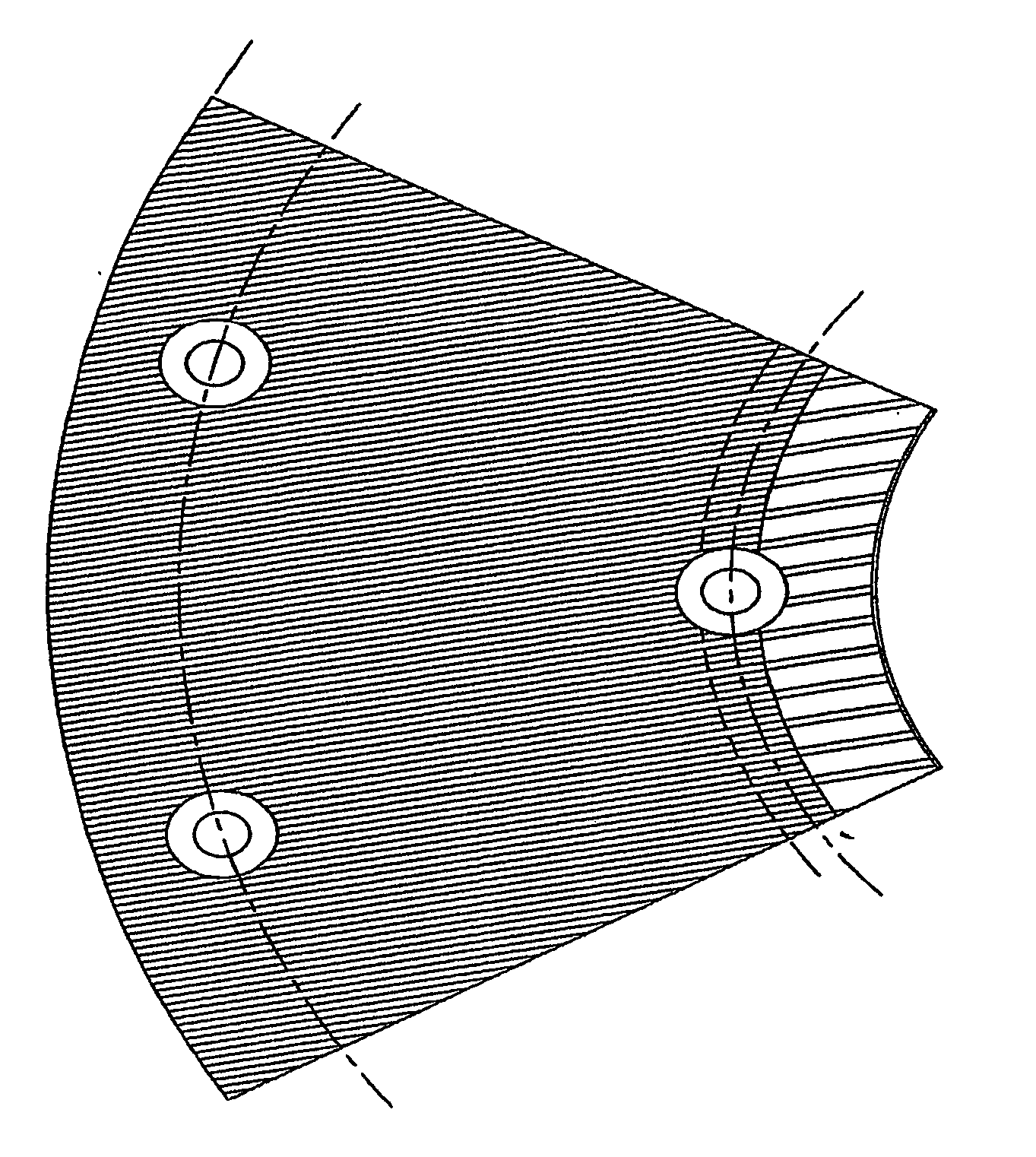
[0026] In general terms, the invention discloses an improved method for the manufacture of a solid rotor disc and / or rotor segment for a single disk refiner, double disk refiner, multi-disk refiner, single cone refiner, or a double cone refiner. The invention comprises a plurality of blade members spaced apart by recessed locations of a base plate. Such locations are preferably grooves cut into, or selectively spaced holes drilled into, the base plate material by either a water jet milling machine, or a horizontal gang mill, or both.

[0027] In the case of disks and segments, the base plates are preferably cut to dimension using CAD / CAM driven water jet cutting technology so as to avoid warping and localized hardening or localized softening of the blades. The blades are cut out of appropriately dimensioned cold rolled and cryogenically stabilized stainless steel or other appropriate stock of the appropriate hardness required by the application through CAD / CAM using either a high watt...


PUM

PropertyMeasurementUnit
Dimensionaaaaaaaaaa
Stress optical coefficientaaaaaaaaaa
Hardnessaaaaaaaaaa

Abstract

An improved method for the manufacture of a solid disc rotor and/or rotor segment for a single disk refiner, double disk refiner, multi-disk refiner, single cone refiner, or a double cone refiner. The invention comprises a plurality of blades spaced apart by recessed locations of a base plate. Either a water jet milling machine or a horizontal gang mill or both may be used. The blades comprise appropriately dimensioned cold rolled and cryogenically stabilized stainless steel or other appropriate stock of the appropriate hardness required by the application. The blades fit into respective locations in the base. The invention is further characterized by a continuous laser weld (85) along either side of each respective blade at its junction with the base, a variety of possible blade and base materials, and the use of one or more of cryogenic treatment, water cut jetting and water jet milling technologies.

Description

CROSS REFERENCE TO RELATED APPLICATION [0001] This application claims the benefit of US provisional patent application No. 60 / 355,329 filed Feb. 7, 2002.TECHNICAL FILED [0002] The invention relates to fiber processing equipment utilized in the wood pulp, paper, and rubber industries. More particularly, the invention relates to the manufacture of any of a solid rotor or disk, segmented rotor or stator, single cone rotor or stator, or double cone rotor or stator, all for a refiner. BACKGROUND [0003] Paper can be manufactured from a variety of materials. Rags or cotton linters, for example, are used for the highest quality paper. Lower quality paper can be made from seed fibres, jute, flax, grass and other plants. The largest amount of paper today, however is made from wood pulp. [0004] Wood pulp manufacture typically begins with cutting trees, trimming the cut trees into logs and de-barking the logs to provide the raw wood material. The logs are then broken into chips. The chips are t...

Claims


Application Information

Patent Timeline
IPC IPC(8): B02C7/12B23K26/00B23K26/24B23P15/00D21D1/24D21D1/26D21D1/30
CPCB02C7/12B23K26/0009B23K26/246D21D1/306B23P15/00D21D1/24D21D1/26B23K2203/04B23K26/0006B23K26/244B23K2103/05B23K2103/50
Inventor THEUT, PATRICK J.
Owner THEUT PATRICK J
Why Eureka
Try Eureka