Plasma display panel

a technology of display panel and plasma, which is applied in the direction of gas discharge vessel/container, address electrode, gas-filled discharge tube, etc., can solve the problems of color interference phenomenon, increase discharge voltage, reduce operation margin, and reduce brightness/efficiency characteristics, so as to improve color temperature and color correction. , the effect of improving the color temperatur

Inactive Publication Date: 2005-07-28
LG ELECTRONICS INC
View PDF4 Cites 4 Cited by
  • Summary
  • Abstract
  • Description
  • Claims
  • Application Information

AI Technical Summary

Benefits of technology

[0017] Accordingly, it is an object of the present invention to provide a plasma display panel that is adaptive for improving a color coordinates correction and a color temperature.

Problems solved by technology

On the other hand, the PDP adopting the stripe-type barrier rib 24 has disadvantages in that it fails to have a high brightness characteristic because an amount of the visible light amount produced by a radiation of the phosphorous material 26 within the discharge cell is small due to a limitation in its area coated with the phosphorous material and in that a width of the gas flowing path between the upper and lower discharge cells is large due to a non-existence of the structure provided between the barrier ribs 24 at a region where the upper and lower discharge cells are divided, thereby causing a cross talk to lead to a color interference phenomenon between the pixels of the PDP.
However, the PDP in which a pitch between the discharge cells for implementing the red(R), green(G) and blue(B) colors has a non-symmetric structure has a problem in that horizontal pitches of the red(R), green(G) and blue(B) discharge cells are too reduced as a resolution of the PDP goes higher, thereby causing an increase of discharge voltage, a reduction of operation margin and a reduction of brightness / efficiency characteristics.

Method used


Image

  • Plasma display panel
  • Plasma display panel
  • Plasma display panel

Examples


Embodiment Construction

[0028] Reference will now be made in detail to the preferred embodiments of the present invention, examples of which are illustrated in the accompanying drawings.

[0029] Hereinafter, the preferred embodiments of the present invention will be described in detail with reference to FIGS. 4 and 5.

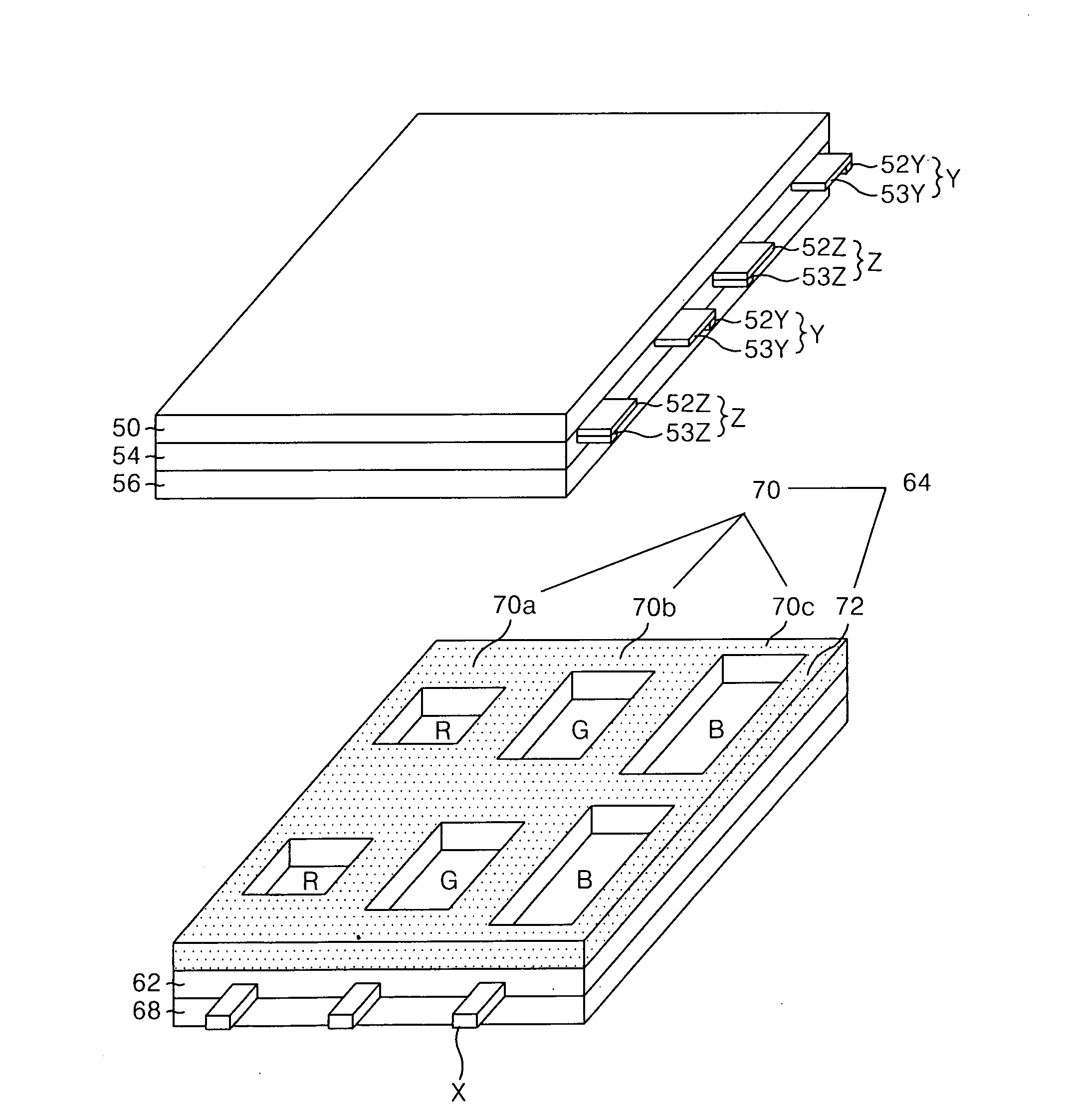
[0030]FIG. 4 is a perspective view showing a structure of a plasma display panel according to an embodiment of the present invention, and FIG. 5 is a plan view of a lower substrate in the plasma display panel shown in FIG. 4.

[0031] Referring to FIG. 4 and FIG. 5, a discharge cell of the PDP according to the embodiment of the present invention includes a scan electrode Y and a sustain electrode Z provided on an upper substrate 50, and an address electrode X provided on a lower substrate 68.

[0032] The scan electrode Y includes a first transparent electrode 52Y, and a first bus electrode 53Y provided at the rear side of the first transparent electrode 12Y. The sustain electrode Z includes a sec...


PUM


Abstract

A plasma display panel for improving a color coordinates correction and a color temperature is disclosed. In the plasma display panel, a vertical barrier rib separates red, green and blue discharge cells from each other in a longitudinal direction. A horizontal barrier rib is provided between the vertical barrier ribs to separate the red, green and blue discharge cells from each other in a wide direction. The horizontal barrier rib has a first horizontal barrier rib provided between the red discharge cells, a second horizontal barrier rib provided between the green discharge cells, and a third horizontal barrier rib provided between the blue discharge cells and having a smaller width than the first and second horizontal barrier ribs.

Description

[0001] This application claims the benefit of Korean Patent Application No. P2003-102178 filed in Korea on Dec. 31, 2003, which is hereby incorporated by reference. BACKGROUND OF THE INVENTION [0002] 1. Field of the Invention [0003] This invention relates to a plasma display panel, and more particularly to a plasma display panel that is adaptive for improving a color coordinates correction and a color temperature. [0004] 2. Description of the Related Art [0005] Generally, a plasma display panel (PDP) radiates a phosphorous material using an ultraviolet ray with a wavelength of 147 nm generated upon discharge of an inactive mixture gas such as He+Xe, Ne+Xe or He+Ne+Xe, to thereby display a picture including characters and graphics. Such a PDP is easy to be made into a thin-film and large-dimension type. Moreover, the PDP provides a very improved picture quality owing to a recent technical development. Particularly, since a three-electrode, alternating current (AC) surface-discharge P...

Claims


Application Information

Patent Timeline
Patent Type & Authority Applications(United States)
IPC IPC(8): H01J11/12H01J11/22H01J11/24H01J11/26H01J11/34H01J11/36
CPCH01J11/12H01J2211/363H01J11/36
Inventor LEE, GI BUMKIM, JIN YOUNG
Owner LG ELECTRONICS INC
Why Eureka
Try Eureka