
Generator of a time-variable magnetic field and magnetic resonance device

a technology of magnetic field and generator, applied in the direction of magnetic measurement, measurement device, instruments, etc., can solve the problems of more compact structure, smaller size, and cost-effective structure, and achieve the effect of reducing h field, efficient generation of magnetic field, and reducing magnetic energy density

Inactive Publication Date: 2005-07-28
SIEMENS HEALTHCARE GMBH
View PDF23 Cites 8 Cited by
  • Summary
  • Abstract
  • Description
  • Claims
  • Application Information

AI Technical Summary

Benefits of technology

The invention is about a new type of generator for magnetic resonance devices that is compact and efficient. The generator has a sub-assembly with magnetizable material that reduces the space needed and the amount of current needed. This makes the device more cost-effective and compact. The sub-assembly also helps to reduce the impact of the magnetic field on adjacent electrical components. Overall, the invention provides a more efficient and compact magnetic resonance device.

Problems solved by technology

This leads to smaller, more compact and thus more cost-effective structures.

Method used


Image

  • Generator of a time-variable magnetic field and magnetic resonance device
  • Generator of a time-variable magnetic field and magnetic resonance device
  • Generator of a time-variable magnetic field and magnetic resonance device

Examples


Embodiment Construction

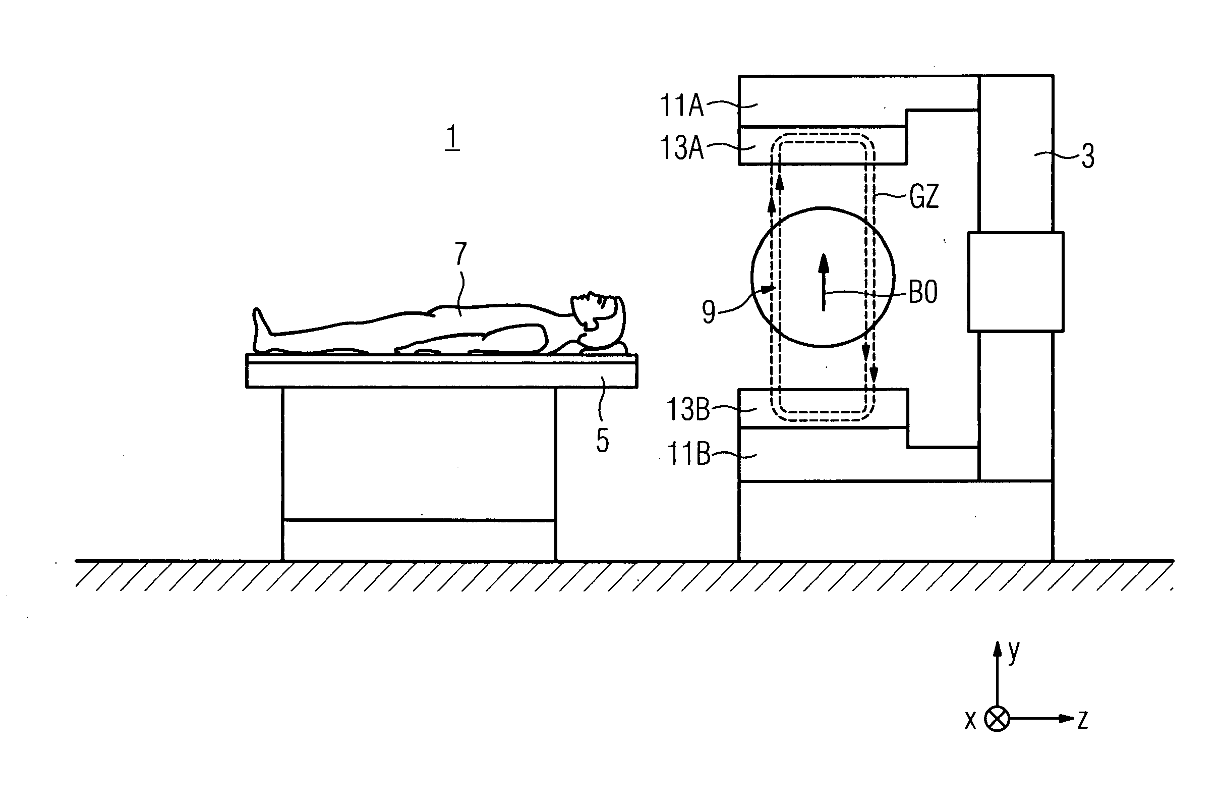
[0027]FIG. 1 shows schematically an open magnetic resonance device 1 for medically examining patients e.g. by means of MR tomography or MR spectroscopy in a main magnetic field B0 which is generated with a C-shaped main field magnet 3. The B0 field, which is constant over time, is generated according to the specified system of coordinates along the Y axis and lies e.g. in the order of 0.3 T. Also shown schematically is a patient bed 5 with which a patient 7 can be entered into the examination space 9. The examination space 9 is arranged in the air gap between two pole elements 11A,11B of the main field magnet 3.

[0028] The pole elements 11A,11B have e.g. solenoid actuators. Gradient-coil HF antenna units 13A,13B adapted to the pole elements 11A,11B generate in the examination space 9 on the one hand gradient fields GZ and on the other B1 high-frequency fields which are oriented perpendicularly to the main magnetic field B0. As an example, magnetic-field lines of a gradient field GZ ...


PUM


Abstract

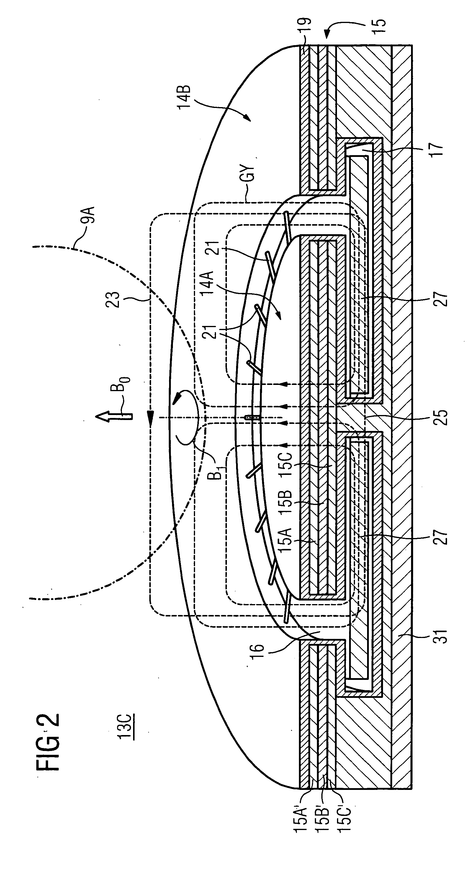
A generator (13A, . . . 13C) of a time-variable magnetic field (B1) of a magnetic resonance device (1) which has an examination space (9,9A) for accommodating at least one area to be examined of an examination subject (7), in which examination area the time-variable magnetic field (B1) is generated by means of a current through a conductor (15, 19, 31). The magnetic field lines (23) of the magnetic field (B1) close with the aid of a field flux return space (17), in which there is arranged at least one sub-assembly (27) which has magnetizable material. A reduction of a magnetic energy density in the field flux return space (17) is produced by this means. This increases e.g. the efficiency i n the generation of high-frequency magnetic fields (B1) or of gradient fields with the aid of the conductor (15,19,31).

Description

CROSS REFERENCE TO RELATED APPLICATIONS [0001] This application claims priority to the German application No. 10 2004 003 535.0, filed Jan. 23, 2004 which is incorporated by reference herein in its entirety. FIELD OF INVENTION [0002] The invention relates to a generator of a time-variable magnetic field of a magnetic resonance device which has an examination space for accommodating at least one area of an examination subject, in which space the time-variable magnetic field is generated. The invention also relates to a magnetic resonance device having a generator of this type. BACKGROUND OF INVENTION [0003] Magnetic resonance technology is a known technology for, among other things, obtaining images of the inside of a body of an examination subject. In a magnetic resonance device (MR device), rapidly switched magnetic gradient fields which are generated by means of gradient coils are superimposed on a static main magnetic field B0 which is generated by a main field magnet. In order t...

Claims


Application Information

Patent Timeline
Patent Type & Authority Applications(United States)
IPC IPC(8): G01R33/34G01R33/38G01R33/421G01R33/422
CPCG01R33/34046G01R33/3806G01R33/422G01R33/4215G01R33/385
Inventor HEID, OLIVERVESTER, MARKUS
Owner SIEMENS HEALTHCARE GMBH
Learn More