Removing ink waste

a technology of ink waste and ink spouting, which is applied in the field of ink waste removal, can solve the problems of unsuitable permanent spittoons, high predicted amount of ink waste, and danger of liquid spillage and environmental considerations, and achieves the effects of reducing the volume of waste products, and reducing the risk of liquid spillag

Inactive Publication Date: 2005-07-28
HEWLETT PACKARD DEV CO LP
View PDF4 Cites 12 Cited by
  • Summary
  • Abstract
  • Description
  • Claims
  • Application Information

AI Technical Summary

Benefits of technology

[0014] Certain aspects of the present invention seek to provide a spittoon arrangement in which the ink waste product is dried relatively quickly. This permits an enhanced reduction in the volume of the waste product. This in turn permits a higher rate of spitting from the printheads. It also reduces the risk of contamination of the hardcopy device and / or a print media by liquid ink being thrown off by movement of a spittoon.
[0020] Certain aspects of the invention seek to provide a spittoon arrangement from which dried ink waste product is removed relatively quickly and efficiently.

Problems solved by technology

Disposing of ink waste materials from a printer usually poses problems regarding satisfactory containment, the danger of liquid spills and environmental considerations.
However, permanent spittoons are unsuitable where there is little space for storage and / or the predicted amount of ink waste is relatively high.
The question of the removal of waste ink product becomes an increasing problem as the number of printhead nozzles increases, as a printer's duty cycles become heavier and as the proportion of pigment in modern inks increases.
The problem directly affects such issues as spittoon size and replacement frequency but also the intervention rate, handling, liquids disposal and machine size.
This is time-consuming and a precise positioning system is required to ensure that the printheads are accurately returned to the correct printing position after a servicing operation has been undertaken.

Method used


Image

  • Removing ink waste
  • Removing ink waste
  • Removing ink waste

Examples


second embodiment

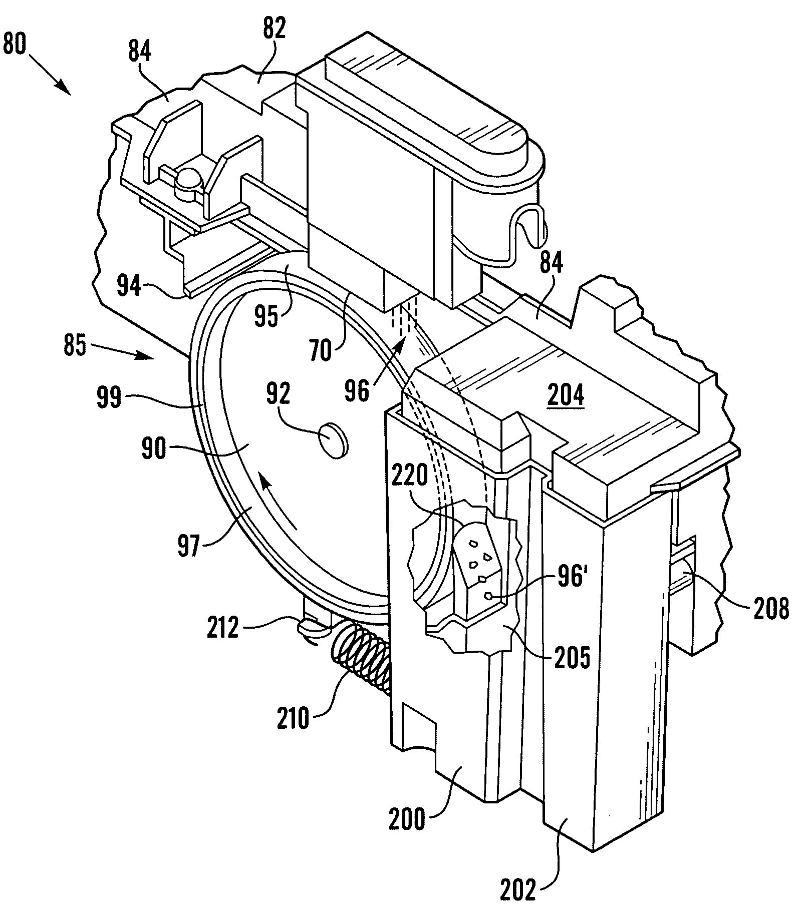
[0066] Referring now to FIG. 7, an ink-jet printer in accordance with the present invention is of the scanning type. Such a printer is disclosed in U.S. Pat. No. 6,340,320. A service station 80 of the printer has a main frame 82 that is supported by a printer chassis in a servicing region within a printer casing. The service station frame 82 has a sidewall 84 which supports a portion of a transferring spittoon system 85 as a portion of the service station 80 for handling waste inkjet ink deposited in particular by a printhead 70. Printhead 70 is mounted on a carriage (not shown) which in use undertakes scanning type movements over a print media.

first embodiment

[0067] A motor and gear assembly (not shown) drives a spittoon wheel portion 90 of the transferring spittoon system 85. The transferring spittoon system 85 includes a spindle or sidewall 84 to rotationally support the spit wheel 90. A back-up wheel scraper 94 extends from the sidewall 84 to stop any accumulation of ink residue, which may have inadvertently adhered to the spit wheel, from passing under and possibly damaging the printhead 70. The spit wheel 90 has an outer rim 95, which preferably has a concave shaped cross section, to serve as a spit platform for receiving waste ink spit 96 from the printhead 70. Preferably, the spit wheel 90 is mounted to receive the ink spit 96 along a descending portion thereof, as the wheel 90 is rotated in the direction of arrow 97. Preferably, the spit wheel 90 is constructed of an ink-resistant, non-wetting material with dimensional stability, such as a glass fiber filled blend of polyphenylene oxide and polyethylene. As part of the rim 95 the...

third embodiment

[0077] Referring now to FIG. 8, a printer 360 in accordance with the present invention comprises a printhead 370 mounted on carriage (not shown) which undertakes scanning movements in the direction indicated by arrow 371 over a print media 15 on a stationary printer platen 377. Print media is moved in a direction perpendicular to the plane of the drawing.

[0078] The printer 360 has a service station section 380 which incorporates a spittoon container 300 mounted to be fixedly attached to the printer chassis. Container 300 has a heater 399. To undertake a spitting operation, printhead 370 is moved beyond the edge of the print media 15 to the position shown in FIG. 8. A spitting operation is undertaken, and ink 396 is ejected into the container 300, where it is then dried by the heater 399. The dried ink residue may be permanently stored in the spittoon container. Alternatively, the spittoon may be provided with a removal member, such as the screw member disclosed in U.S. Pat. No. 6,34...


PUM


Abstract

A hardcopy device such as an ink-jet printer comprises a printhead, a spittoon for receiving waste ink from the printheads, and a heater for quickly drying the ink waste products in the spittoon. A drum platen having a print media supporting area also has an elongate spittoon region extending across its circumferential surface, the contents of the spittoon region being arranged to be removed intermittently by an elongate scraper which, in one position of the drum, can be moved radially towards the drum to contact the spittoon region.

Description

[0001] The present invention relates to the removal of ink waste from hardcopy devices such as inkjet printers. BACKGROUND OF THE INVENTION [0002] When a hardcopy device such as an inkjet printer is not in use, pigment in the ink in its printheads tend to be deposited around each printhead nozzle leaving relatively thin ink, i.e. with a higher proportion of solvent, in the nozzle itself. To avoid deterioration in print quality after a period of non-use, a servicing operation needs to be undertaken to ensure correct operation of the nozzle immediately on commencement of a subsequent printing operation. This typically involves wiping of the nozzle with an elastomeric wiper blade and the spitting of some drops of ink from the nozzle so that it contains ink of the required formulation. The wasted drops of ink are captured within a device known as a spittoon. [0003] The spittoon needs to be of a size corresponding at least to the maximum amount of ink it is expected to contain. Disposing...

Claims


Application Information

Patent Timeline
Patent Type & Authority Applications(United States)
IPC IPC(8): B41J2/18B41J2/165B41J2/185B41J11/04
CPCB41J2/16523B41J2002/1742B41J2/16541B41J2/185
Inventor GASTON, GONZALOMONCLUS, ANTONIOVALLES, LLUISSOLE, MACIA
Owner HEWLETT PACKARD DEV CO LP
Why Eureka
Try Eureka