
System and method for generating images on ferromagnetic materials

Inactive Publication Date: 2005-07-28
WARDKRAFT
View PDF7 Cites 6 Cited by
  • Summary
  • Abstract
  • Description
  • Claims
  • Application Information

AI Technical Summary

Benefits of technology

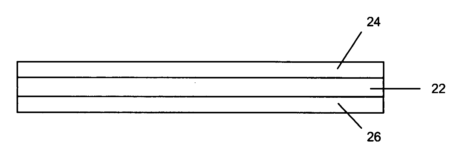
[0020] The present invention provides a method and system for producing a unique item from a substrate created from a laminated configuration that is suitable for creating advertising, memorabilia, remembrance items, souvenirs and the like. The magnetic laminate when used in the present system of the present invention overcomes the foregoing drawbacks by producing a product that is readily and cleanly removable from the construction as well as provides a laminate that can be processed efficiently by a manufacturer or user without the necessity of supplemental processing steps or the inclusion of auxiliary materials or suffer from increased weight for shipping / handling purposes.

Problems solved by technology

This demand also has presented the manufacturer with the difficulties of including this auxiliary magnetic material with traditional forms and product stocks such as pressure sensitive materials.
In addition to the difficulties associated with having to add what amounts to a large “chunk” or piece of material, one which typically ranges from 12 to 14 mils, onto a substrate is that the magnetic materials when placed in a stack can create a sloped stack (one side of the stack higher than the other due to the increased thickness of the magnetic material) as well as a stack that is difficult to align or handle due to the magnetic fields created by the coercive forces between poles in successive magnetic sheets.
This can cause the sheets to splay or shift out of alignment making repetitive and continuous feeding through processing equipment difficult and often substantially reducing the efficiency of a manufacturing operation to a series of incremental production of stops and starts so as to accomplish the completion of the job.
The difficulty associated with such prior art constructions is that this construction is often limited in usage to the one advertising arrangement provided with the assembly.
Due to the increased thickness of the magnetic material, the substrate along with the magnet attached thereto cannot easily pass through a laser or other non-impact printer due to the “hump” or “bump” created by the magnet.
This hump can distort the printing of the substrate and potentially cause excessive wear and tear to the print head of the printer due to the abrupt contact with the raised area of the magnet.
As might be expected, this can create alignment problems if the magnetic material is applied to the incorrect area of the substrate.
These products suffer from several drawbacks.
Where the product is to be used as a remembrance item, it is highly undesirable to have an item which produces a less than desirable aesthetic feature.
Secondly, a construction having such a differential height arrangement can cause problems for printing and processing equipment as discussed above.
In addition, the concept utilized by the '474 application would not enable the subsequent processing of the material due to the differential thickness of the magnet on the card or stock.
However, in order to process this particular construction the magnetic material is provided in a deadened state, one in which there is no readily discernable magnetic force or alternatively it is so weak that the magnetic material as provided is incapable of adhering to a metallic surface.
As expected, the additional step of charging the magnet is time consuming and adds a further layer of expense to the offering being presented.
In addition, even after the charging, the magnetic sheets are difficult to handle and cannot be wrapped in a flat stack as the coercive forces of each of the magnetic pole regions causes successive sheets to splay or shift out of alignment with one another.
However, in addition to the added costs of the thicker material or inserts, there is the added cost associated with transporting and shipping the material due to the increased thickness or inserts.
This construction unfortunately suffers from the drawback that the magnet may not adhere to the desired surface due to the relatively weak field.
Where it has been tried to create an image on a magnetic sheet, that retains a charge, the charge present in the sheet can cause the sheet to migrate out of alignment with the image generator, thus causing the image to appear off center, or be partially cut off.
This unfortunately leads to significant waste and disappointment.
In addition, where such sheets can be successfully printed, the sheets have a tendency to “lock up” or stick together making quick separation and distribution difficult.
However, this will then likely require the sheets to be magnetized after imaging leading to an increase in processing costs due to the extra handling required as well as the amortization of the equipment.
These particular constructions also rely on significantly thicker magnetic material in forming the substrate and as might be expected this substantially increases the weight of the material for shipping and handling purposes.

Method used


Image

  • System and method for generating images on ferromagnetic materials
  • System and method for generating images on ferromagnetic materials
  • System and method for generating images on ferromagnetic materials

Examples


Embodiment Construction

[0032] The present invention is now illustrated in greater detail by way of the following detailed description which represents the best presently known mode of carrying out the invention. However, it should be understood that this description is not to be used to limit the present invention, but rather, is provided for the purpose of illustrating the general features of the invention.

[0033] As used herein the term “remembrance” item, article or element includes but is not limited to memorabilia, advertising and marketing collateral, souvenirs, tokens, trophies and certificates, keepsakes, reminders and generally other images and indicia that are intended to call to mind something about the provider of the product or the image or indicia printed or produced on the surface of the product.

[0034] As used herein the terms “capture” or “generating” as it relates to the capture, generation or collection of images can include digital means, cameras, scanners, optical devices and such oth...


PUM

PropertyMeasurementUnit
Thicknessaaaaaaaaaa
Shapeaaaaaaaaaa
Areaaaaaaaaaaa

Abstract

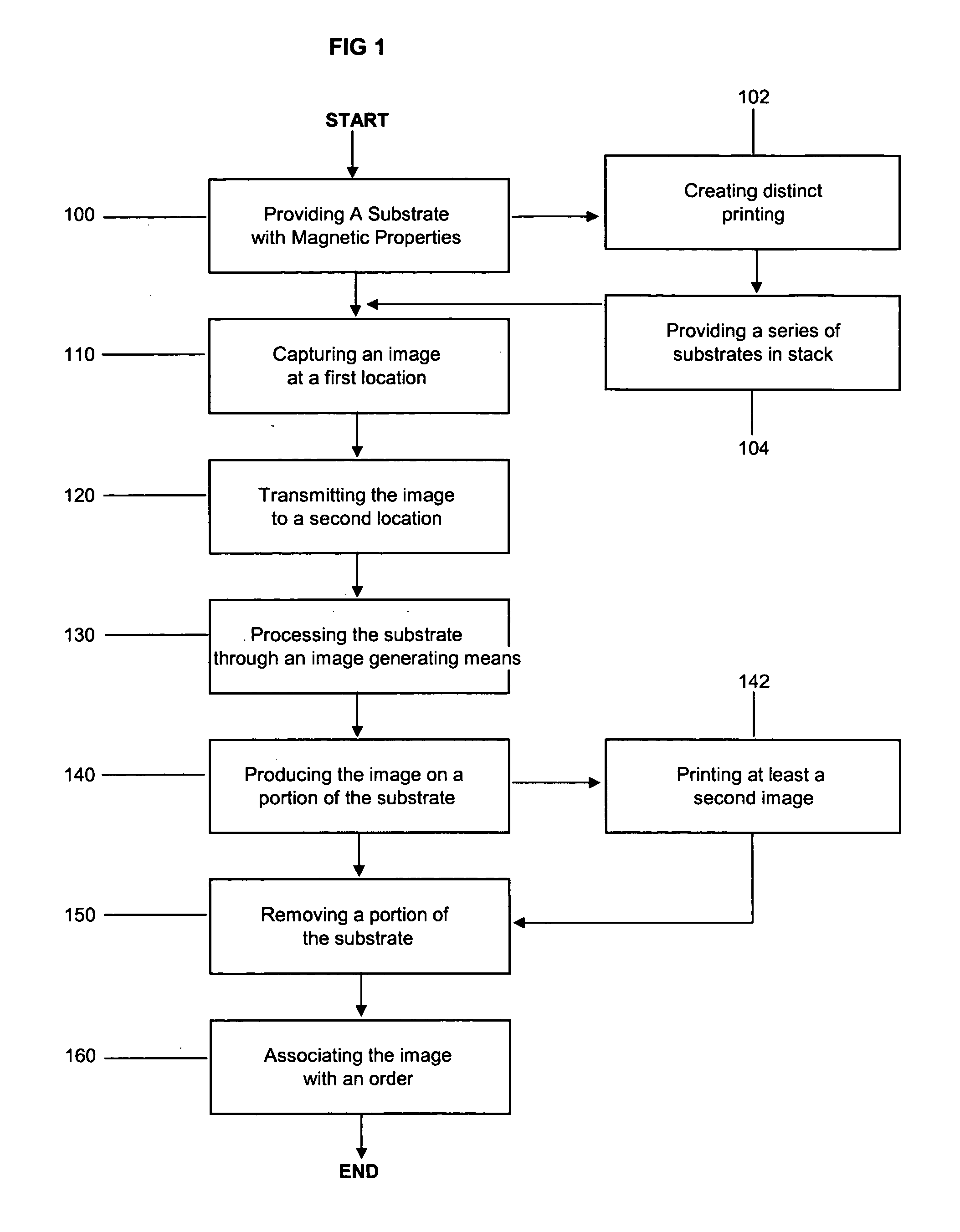
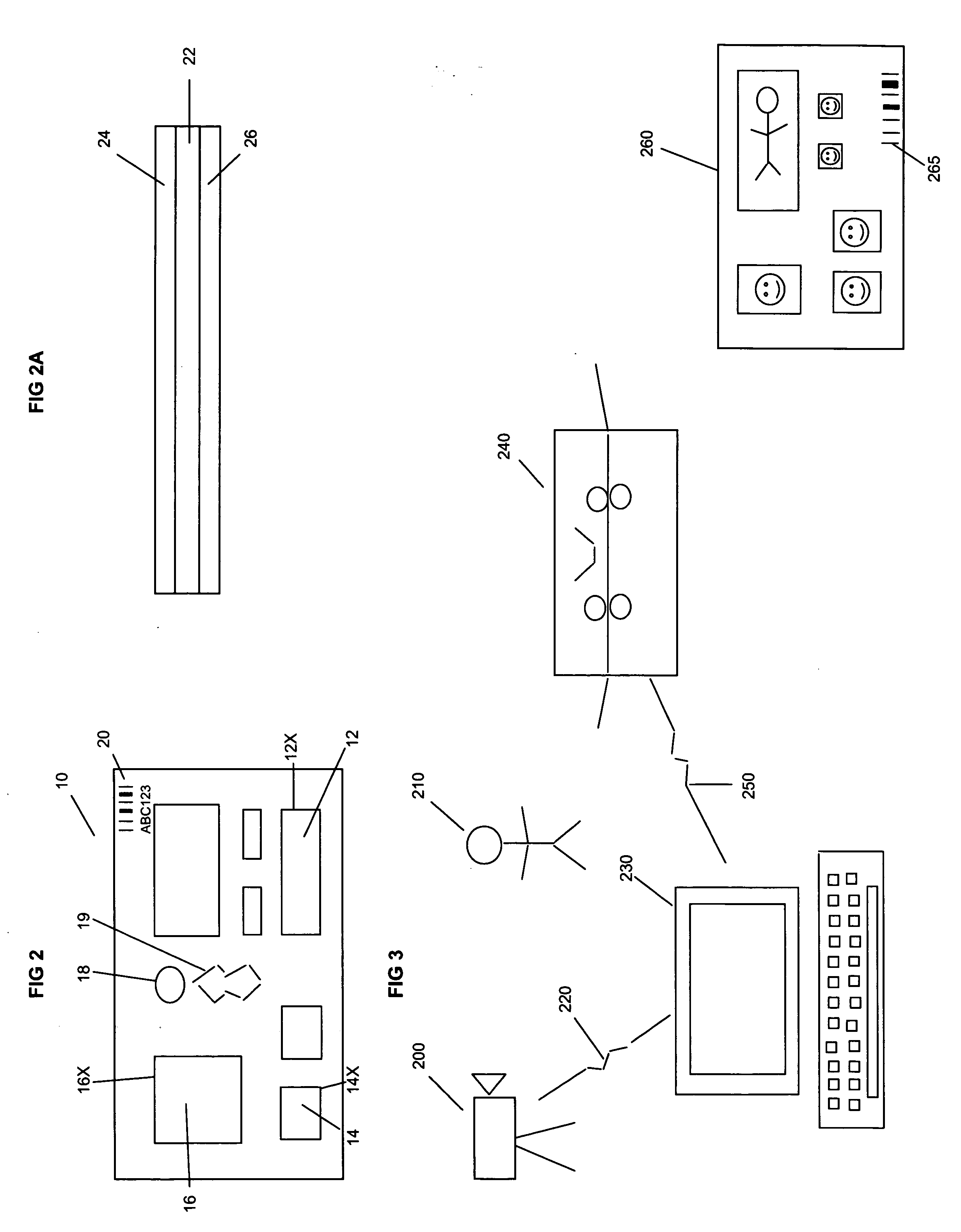
A system and method for creating magnetic remembrance items in an efficient manner is disclosed and includes a substrate having a printable face, a curable base layer and a magnetic core. The substrate may be divided into a number of predetermined areas with each of the areas separated from one another through the use of attenuating lines. The system captures an image, such as a photograph, at a first location and transmits the image to a second location where a digital press is located. A computer collects, manipulates the image and sends print signals to the digital press to render the image in at least one of the predetermined areas to create a removable remembrance element.

Description

CROSS-REFERENCES TO RELATED APPLICATIONS [0001] This application is a continuation-in-part of application Ser. No. 10 / 766,729 filed Jan. 28, 2004 (having a common inventor and assigned to the same assignee as the present application) which is hereby incorporated by reference herein as is necessary for a complete understanding of the present invention.FIELD OF THE INVENTION [0002] The present invention relates to a system and method for creating images, such as photographs and the like on a removable portion of a substrate having ferromagnetic properties. The substrate may be provided in either sheet form or a continuous format and may contain a number of predisposed or predetermined positions that are suitable for receiving discrete images, with each position surrounded by attenuating lines. The substrates may be fed easily to a variable or digital printing system which provides images to the substrate on processing. BACKGROUND OF THE INVENTION [0003] The use of magnetic pieces and ...

Claims


Application Information

Patent Timeline
IPC IPC(8): B05D5/12B32B7/06B41M5/00B41M7/00G06F15/76G09F7/04
CPCB41M5/00G09F7/04B41M7/0072B41M5/41B41M5/508B41M5/52G06F15/76
Inventor CRUM, JESSE D.
Owner WARDKRAFT
Learn More