Small swing type shovel

a swing type and shovel technology, applied in the direction of electric propulsion mounting, transportation items, jet propulsion mounting, etc., can solve the problems of engine inoperativeness, accumulation of impurities at the bottom of the tank, etc., to facilitate pipe arrangement, reduce pressure loss in the pipes, and save space for devices

Inactive Publication Date: 2005-08-04
KOBELCO CONSTR MASCH CO LTD
View PDF3 Cites 18 Cited by
  • Summary
  • Abstract
  • Description
  • Claims
  • Application Information

AI Technical Summary

Benefits of technology

[0030] In addition, it is preferable that the rear row devices be arranged laterally in the order of hydraulic pump, power source and cooling device, while the front row devices be arranged laterally in the order of fuel tank, swivel joint, hydraulic oil tank and control valve, the fuel tank being arranged under the floor of an operator cab disposed in the upper rotating body and the hydraulic pump being located in a rear side of the fuel tank. In this case, in addition to the advantage of the present invention as described above, it is possible to arrange a short and simple return pipe for putting pressure oil from the control valve back to the hydraulic oil tank, whereby the back pressure of the control valve can be kept at low level. Generally, in the case of a high back pressure of control valve, the discharge resistance of pressure oil causes heat generation and the back pressure is added to supplied pressure from hydraulic pump, resulting in an increase in power required for the hydraulic pump, which consequently runs counter to the saving of energy. Also, there is a possibility of having negative impacts on all aspects of the hydraulic pressure control circuit, such as a case that desired force cannot be obtained when operating each hydraulic actuator. Hence, in the present invention is used a short return pipe, which enables the troubles above to be overcome.
[0031] Further, it is possible to dispose a suction pipe that communicates the hydraulic pump and the hydraulic oil tank and a delivery pipe that communicates the hydraulic pump and the control valve between the rear row devices and the front row devices almost linearly, whereby the arrangement of pipes is facilitated and pressure loss in the pipes can be reduced. In particular, the suction pipe has a large diameter, and therefore arranging the pipe with less number of bends has advantages in terms of ensuring the easiness of the arrangement. In addition, although it is often the case that rotating frame is formed into a substantially circular shape to obtain as much an arrangement space for devices on the upper rotating body as possible, the size of the control valve is relatively small, in accordance with the present invention, disposed on the outside of the hydraulic oil tank that requires a large space, whereby the control valve can be arranged along the arc-shape of the rotating frame, improving the usability of the space.
[0032] Furthermore, the fuel tank is arranged under the floor of the operator cab, which allows effective use of the arrangement space for devices on the upper rotating body. In addition, the hydraulic oil tank is arranged between the floor of the operator cab and the control valve, whereby it is avoided that noises such as working oil flowing sound and restricting sound from the control valve reach operators in the operator cab to reduce the comfort therein.
[0033] As described above, in accordance with the present invention, major devices can be arranged effectively in a small swing type excavator with a small arrangement space for devices, providing a saving of energy at the same time and also giving advantages in terms of controlling a hydraulic circuit, and further noises that may reach operators can be limited.
[0034] It is preferable that a battery be disposed on the outside of the fuel tank in the lateral direction. In this case, it is possible to shorten the arrangement space for devices longitudinally, giving advantages in terms of forming a small swing type excavator in which the rear end thereof is within the vehicle width. Also, the battery, which requires to be maintained appropriately, is arranged outside the fuel tank, which facilitates the maintenance of the battery as well as, for example when cleaning the fuel tank, the detachment of the fuel tank by detaching the battery. In particular, since the fuel tank is less often maintained than the battery, the arrangement above is found to be effective.
[0035] It is preferable that an air conditioner be disposed over the floor of the operator cab, for example, under the operator seat, or in a cabin if provided for the operator cab. In this case, the space under the floor of the operator cab can be used more effectively, that is, for example, the volume of the fuel tank can be increased. Although small swing type excavators having a canopy, in which the space over the floor of the operator cab is opened outward, include no air conditioner, the space under the floor of the operator cab can be used effectively even in such a case.

Problems solved by technology

Meanwhile, in the case of fuel tanks that are frequently filled with oil at work sites, there is a possibility that impurities (sand, mud, etc.) may be mixed thereinto when fueling, resulting in an accumulation of the impurities at the bottom of the tanks with age.
The accumulation of the impurities blocks a fuel suction port for an engine as a motor, making the engine inoperative.

Method used


Image

  • Small swing type shovel
  • Small swing type shovel
  • Small swing type shovel

Examples


first embodiment

[0052] (a) First Embodiment

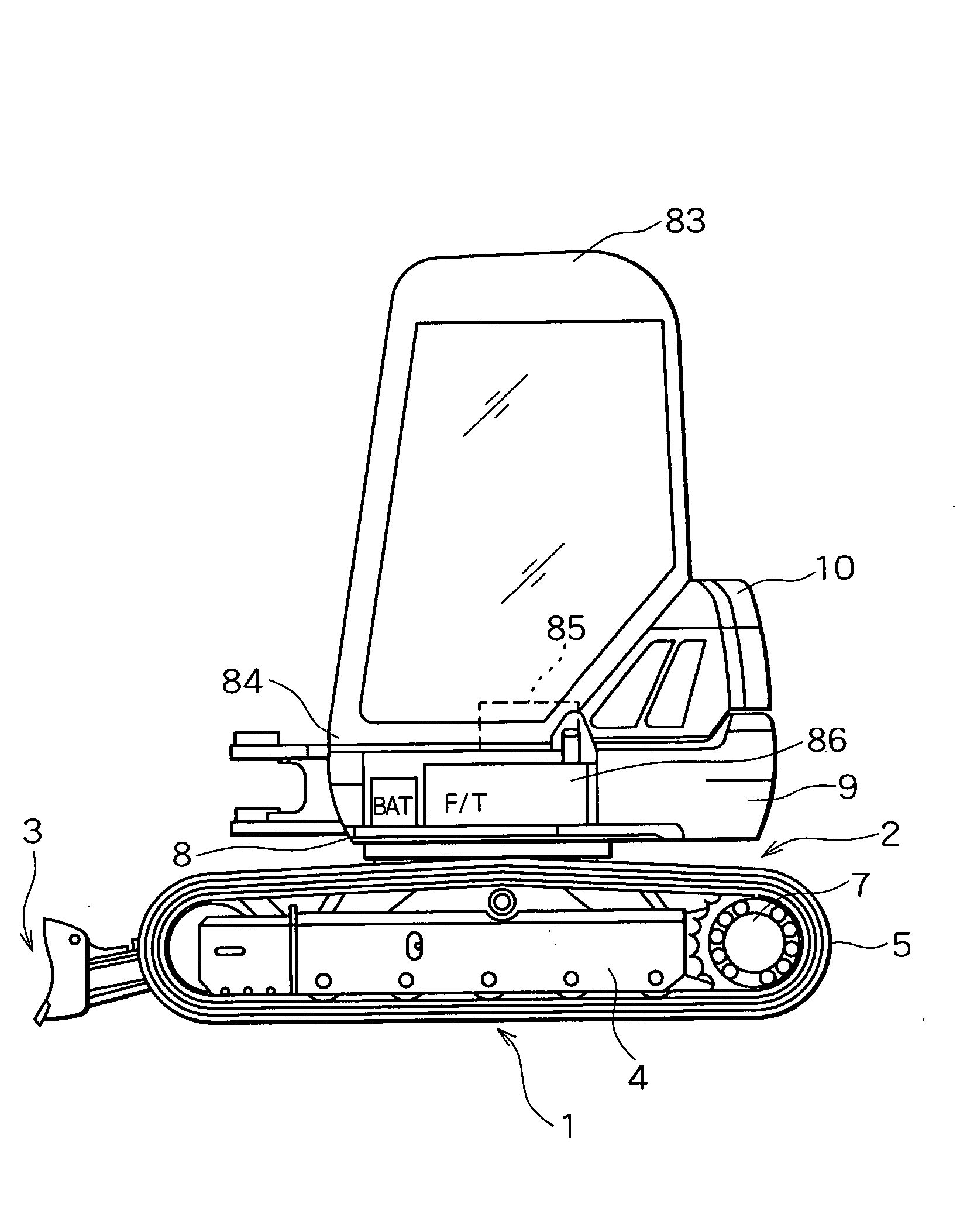
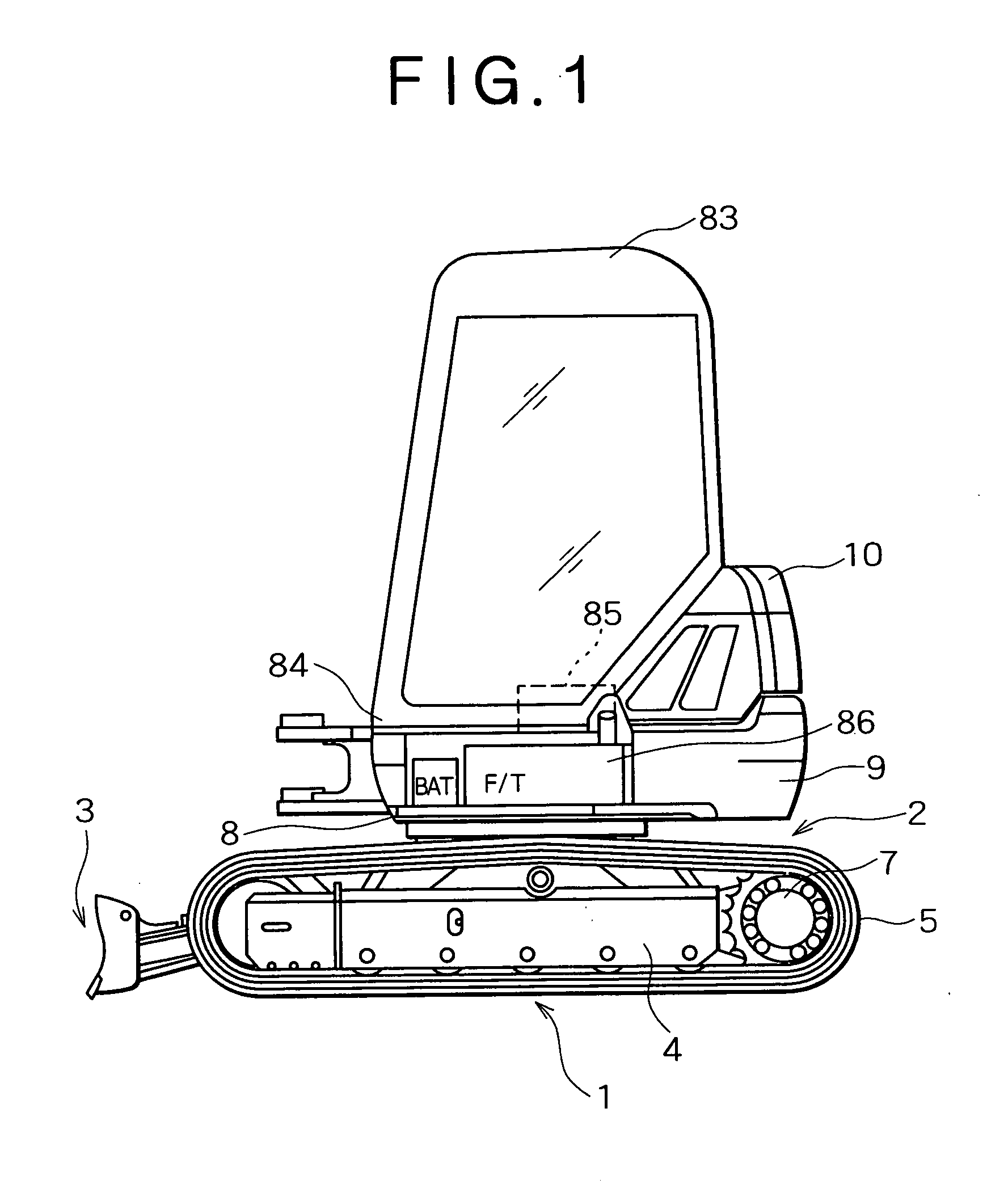
[0053]FIG. 1 shows the overall construction of a so-called small swing type or short-radius excavator among various types of small hydraulic excavators, in which the vehicle body of the short-radius excavator consists of a lower traveling body 1, an upper rotating body 2 mounted rotatably around a vertical shaft on the lower traveling body 1, an excavating attachment not shown in the figure consisting of, for example, a boom pivoted movably in the lateral direction at a support member of a working device that is provided at the front end of the upper rotating body 2 in a protruding manner, and a dozer 3 pivoted movably in the vertical direction to the lower traveling body 1, etc.

[0054] The lower traveling body 1 consists of right and left crawler frames 4 and crawlers 5 (only one side, respectively, thereof is shown in the figure), the crawlers 5 on the both sides being driven rotationally separately by right and left traveling motors 7 to run the vehicle...

second embodiment

[0083] (b) Second Embodiment

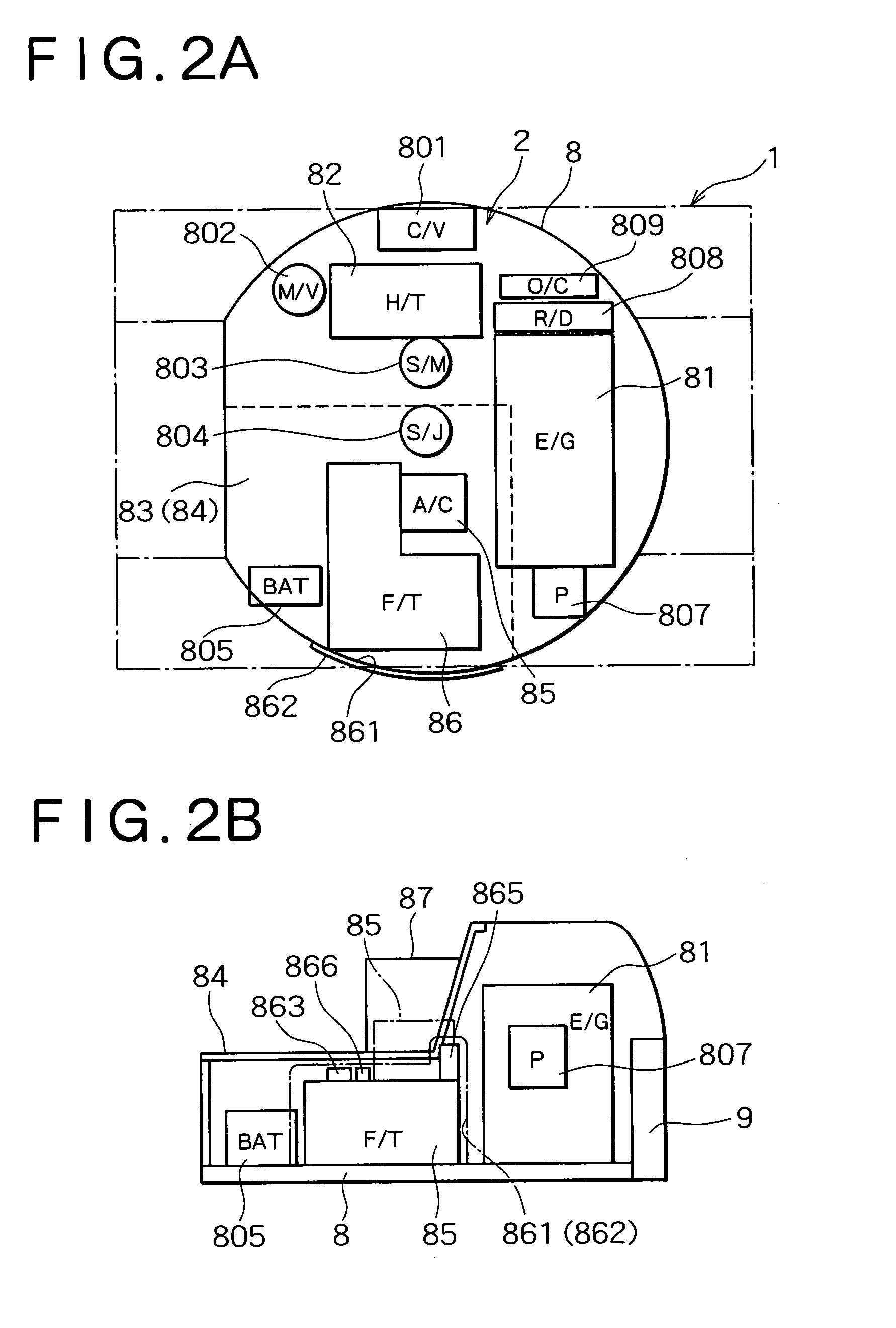
[0084] The device layout in a rotating frame 8 that characterizes the present second embodiment will be described in detail with reference to FIGS. 5A and 5B. It is noted that the left side in FIG. 5A corresponds to front side, the right side to rear side, the upper side to right side, and the lower side to left side, and for the sake of convenience, the same numerals are assigned to components in FIGS. 5A and 5B in common with those in the first embodiment above.

[0085] The configuration of the rotating frame 8 shown in FIGS. 5A and 5B is the same as that of the first embodiment. The floor 84 is represented by the dashed line in FIG. 5A.

[0086] In the present second embodiment, an engine (E / G) 81 as a power source is disposed in the rear section of the rotating frame 8, though in a laterally stretched long attitude, in a slanted manner where both the lateral ends are longitudinally shifted each other so that the longitudinal direction thereof is arranged...

third embodiment

[0101] (c) Third Embodiment

[0102] The device layout in a rotating frame 8 that characterizes the present third embodiment will be described in detail with reference to FIGS. 7A and 7B. It is noted the left side in FIG. 7A corresponds to front side, the right side to rear side, the upper side to right side, and the lower side to left side, and for the sake of convenience, the same numerals are assigned to components in FIGS. 7A and 7B in common with those in the first and second embodiments above.

[0103] The configuration of the rotating frame 8 shown in FIGS. 7A and 7B is the same as that of the first and second embodiments. The floor 84 is represented by the dashed line in FIG. 7A.

[0104] In the present third embodiment, a hydraulic pump (P) 807, an engine (E / G) 81, a radiator (R / D) 808, and an oil cooler (O / C) 809 are disposed in a line from the left to right side in this order as rear row devices in the rear section of the rotating frame 8; and in front of the rear row devices, a...


PUM


Abstract

The present small swing type excavator is characterized by comprising an engine (81) disposed in the rear section of a rotating frame (8) in such a condition that the longitudinal direction thereof is directed to the lateral direction of the rotating frame (8), a hydraulic oil tank (82) disposed on one lateral side in front of the engine (81), a cabin (83) disposed on the other lateral side, an air conditioner (85) disposed under a floor (84) of the cabin (83) and having two surfaces facing to, respectively, the front side and the left outer side of the rotating frame (8), and a fuel tank (86) formed so as to be arranged along at least two surfaces of the front and left side surfaces of the air conditioner (85) and detachably attached to the rotating frame (8).

Description

TECHNICAL FIELD [0001] The present invention relates to a small swing type excavator, wherein an upper rotating body rotates in such a condition that the rear end thereof hardly projects outside the width of a lower traveling body. BACKGROUND ART [0002] Among various types of a small hydraulic excavators, so-called small swing type or short-radius excavator, wherein a rear end rotating radius of an upper rotating body is set to about ½ of the width of a lower traveling body, can rotate 360 degrees in such a condition that the rear end of the upper rotating body hardly projects outside the width of the lower traveling body, which is therefore suitable for work in narrow places such as urban work or subway work. In such a short-radius excavator as above, there is a severe restriction on the longitudinal length of the upper rotating body in comparison with common small hydraulic excavators in which the rear end of the upper rotating body projects outside the width of the lower travelin...

Claims


Application Information

Patent Timeline
Patent Type & Authority Applications(United States)
IPC IPC(8): B60K15/073E02F3/34E02F9/08E02F9/16
CPCB60K15/073E02F9/163E02F9/0883E02F3/325
Inventor TANAKA, KIYOKAZUSAKITANI, SHINTAROOKUNISHI, TAKAYUKIMORITA, HIROSHISHIMOKAKIUCHI, HIROSHI
Owner KOBELCO CONSTR MASCH CO LTD
Why Eureka
Try Eureka