

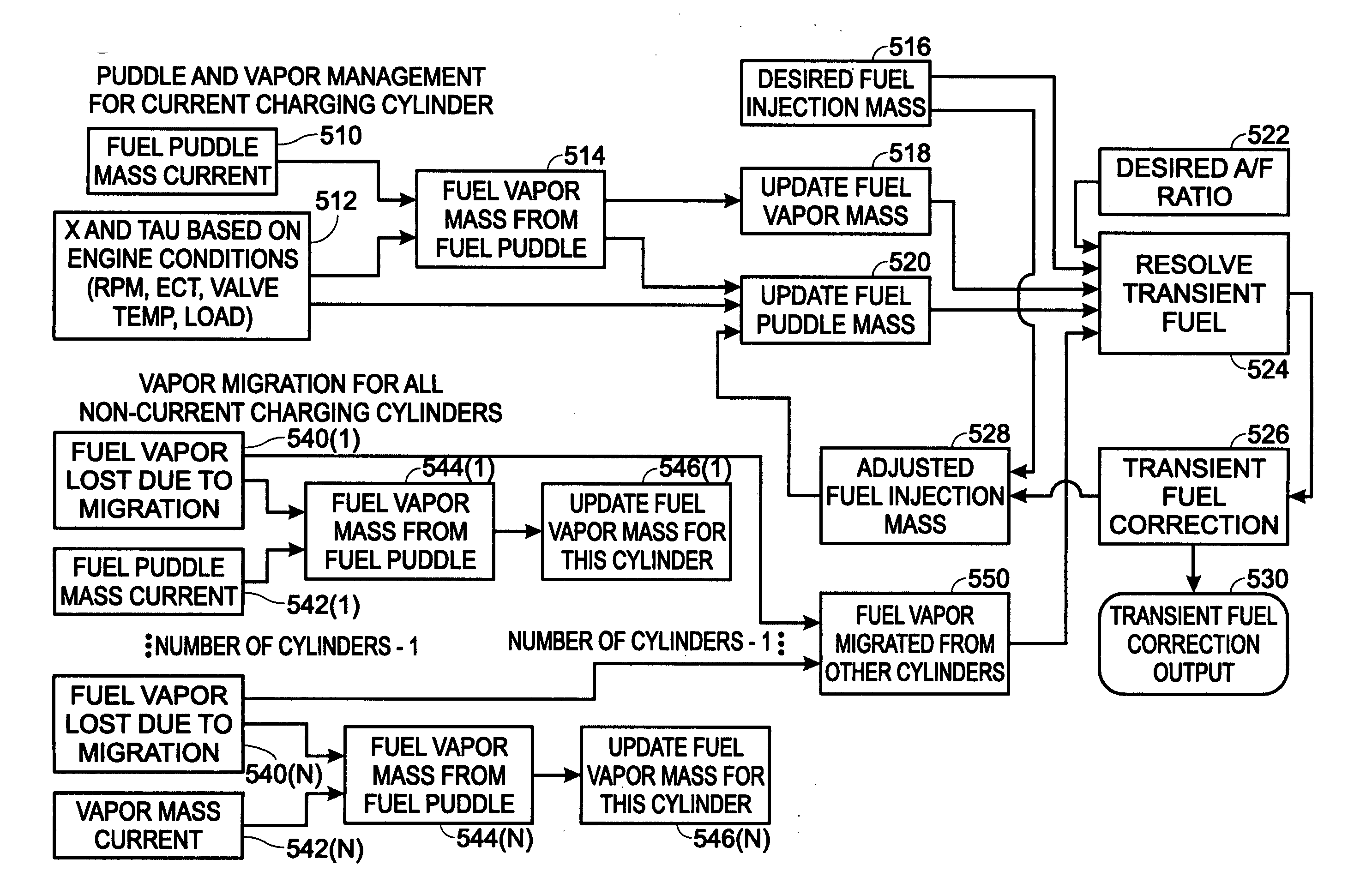
Engine control to compensate for fueling dynamics
a fuel injection compensation and engine technology, applied in electrical control, machines/engines, non-mechanical valves, etc., can solve the problems of inability to accurately control the air-fuel ratio of the active cylinder, not all injected fuel enters the combustion chamber, and errors can occur, etc., to achieve more accurate air-fuel ratio control, more accurate fueling to the active cylinder, and more accurate fueling
- Summary
- Abstract
- Description
- Claims
- Application Information
AI Technical Summary
Benefits of technology
Problems solved by technology
Method used
Image

Examples
Embodiment Construction
)
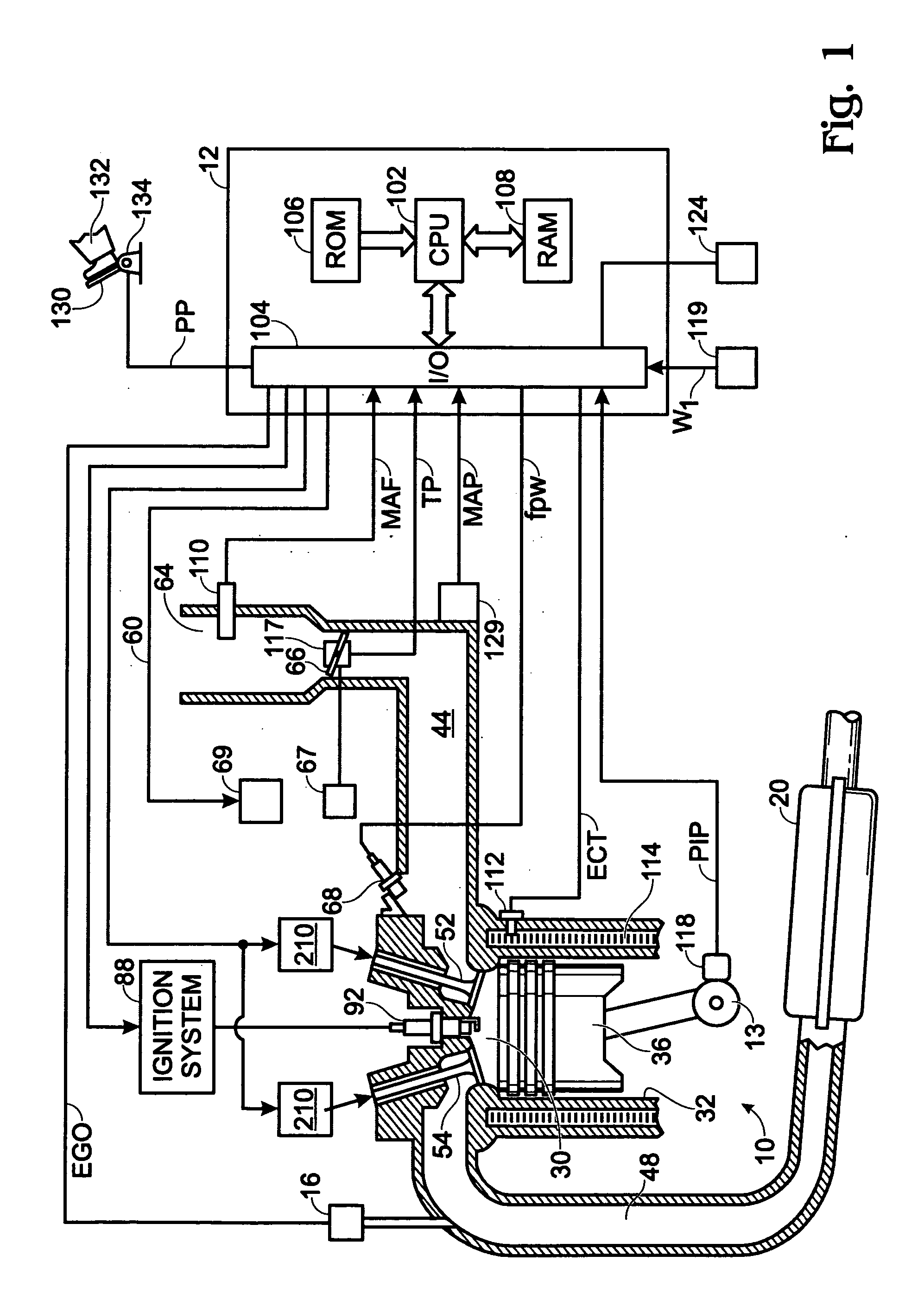
[0020] Referring to FIG. 1, internal combustion engine 10 is shown. Engine 10 is an engine of a passenger vehicle or truck driven on roads by drivers. Engine 10 is coupled to torque converter via crankshaft 13. The torque converter is also coupled to transmission via turbine shaft. The torque converter has a bypass clutch which can be engaged, disengaged, or partially engaged. When the clutch is either disengaged or partially engaged, the torque converter is said to be in an unlocked state. The turbine shaft is also known as transmission input shaft. The transmission comprises an electronically controlled transmission with a plurality of selectable discrete gear ratios. The transmission also comprises various other gears such as, for example, a final drive ratio. The transmission is also coupled to tires via an axle. The tires interface the vehicle to the road.
[0021] Internal combustion engine 10 comprising a plurality of cylinders, one cylinder of which, shown in FIG. 1, is contr...
PUM
 Abstract
Description
Claims
Application Information