Exhaust system for open front fireplace

a technology for exhaust systems and open fireplaces, which is applied in the field of exhaust systems for open fireplaces, can solve the problems of unreachable ventilation, waste products such as carbon monoxide, reaching too high levels within the structure, and occupants could die, and achieve the effect of promoting more efficient heat retention

Inactive Publication Date: 2005-08-04
HNI TECH INC
View PDF26 Cites 4 Cited by
  • Summary
  • Abstract
  • Description
  • Claims
  • Application Information

AI Technical Summary

Benefits of technology

[0008] The present invention generally relates to heating appliances, and more particularly relates to a venting system for a heating appliance combustion chamber. The venting system of the present invention may be useful for venting waste products from an open front combustion chamber, promoting more efficient retention of heat generated by the heating appliance, and providing a safety system to ensure the waste products produced are not released into a living space in proximity to the heating appliance. Although the present invention may be especially useful in a heating appliance with an open front combustion chamber, many principles of the present invention may be applied to heating appliances with a sealed combustion chamber or heating source enclosure.

Problems solved by technology

An occupant could die if waste products, such as carbon monoxide, reach too high of levels within the structure.
An unsealed combustion chamber has the potential of spilling large amounts of waste products into the structure.
Further, the more spread out the combustion is within the combustion chamber (e.g., a fully lit burner plate across the combustion chamber verses a single flame in the center of the combustion chamber), the higher the likelihood that spillage will occur.
Because of the safety requirements for many heating appliances, an open combustion chamber is no longer an option given these potential spillage problems.
Many known exhaust systems do not make an efficient use of waste product heat that is collected before exhaustion of the waste products from the structure.
Although such systems may be useful for capturing some additional heat produced by the heating device, these methods are often ineffective; resulting in much of the heat generated being discharged with the waste product outside of the structure.

Method used


Image

  • Exhaust system for open front fireplace
  • Exhaust system for open front fireplace
  • Exhaust system for open front fireplace

Examples


Embodiment Construction

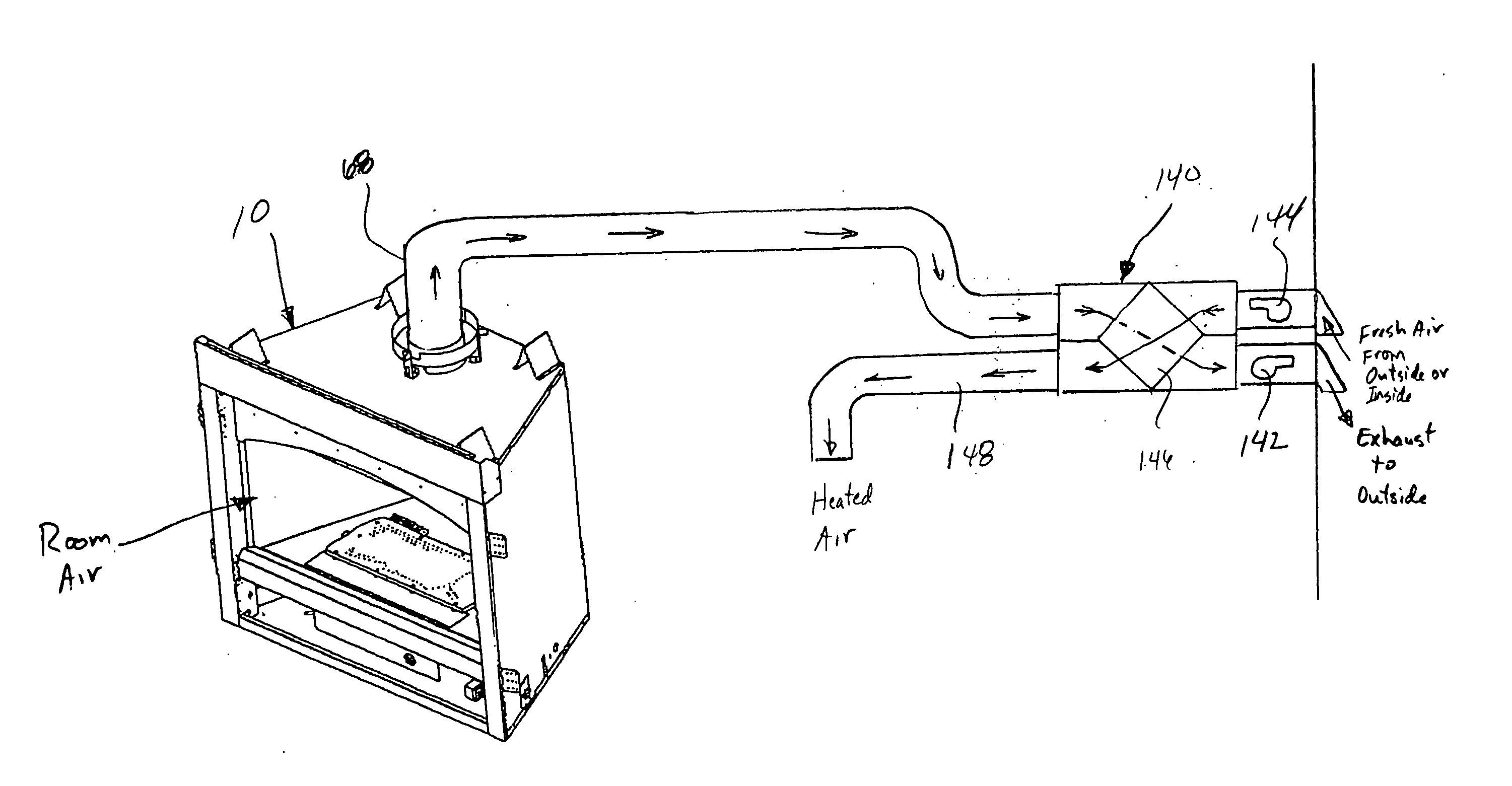
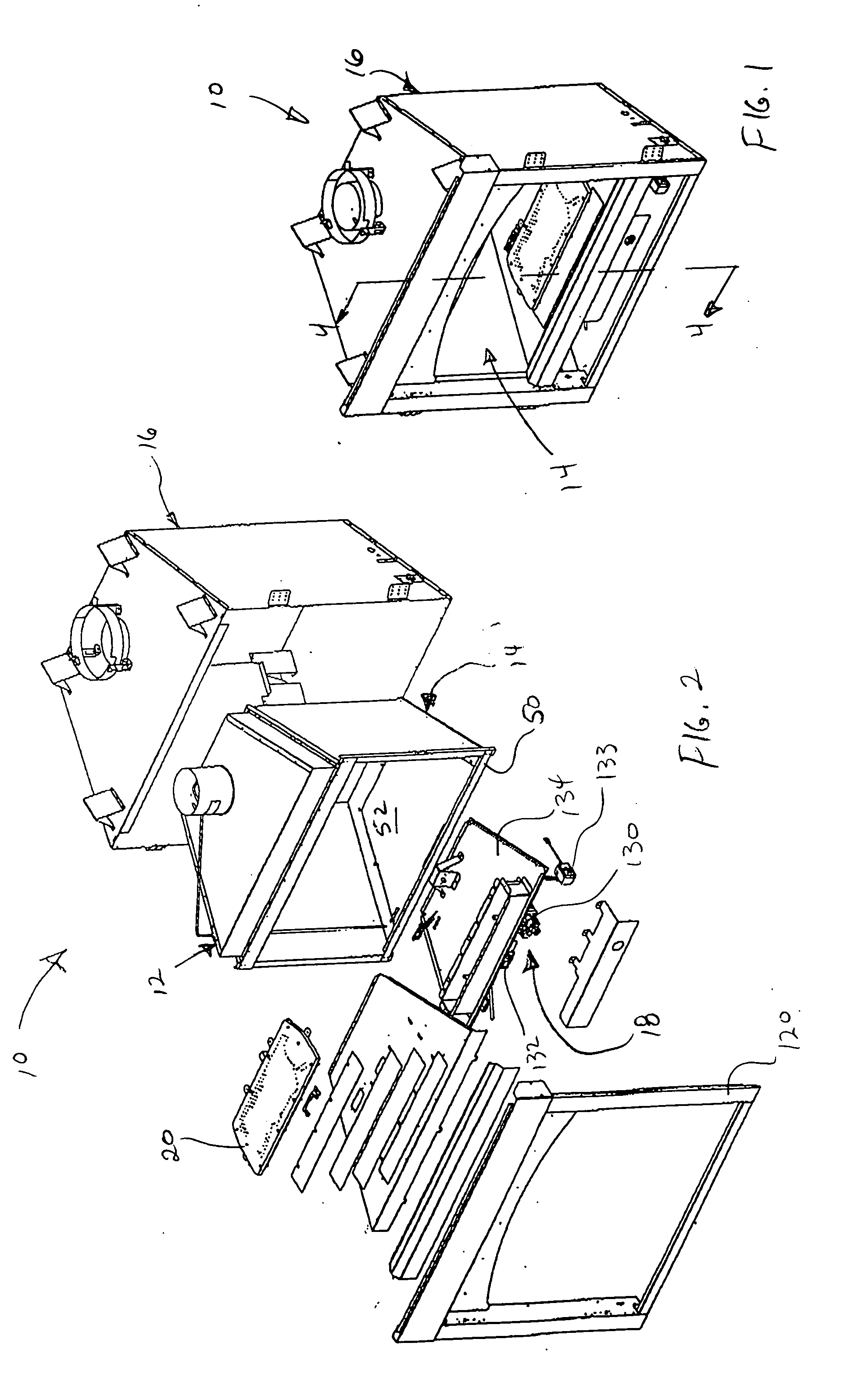
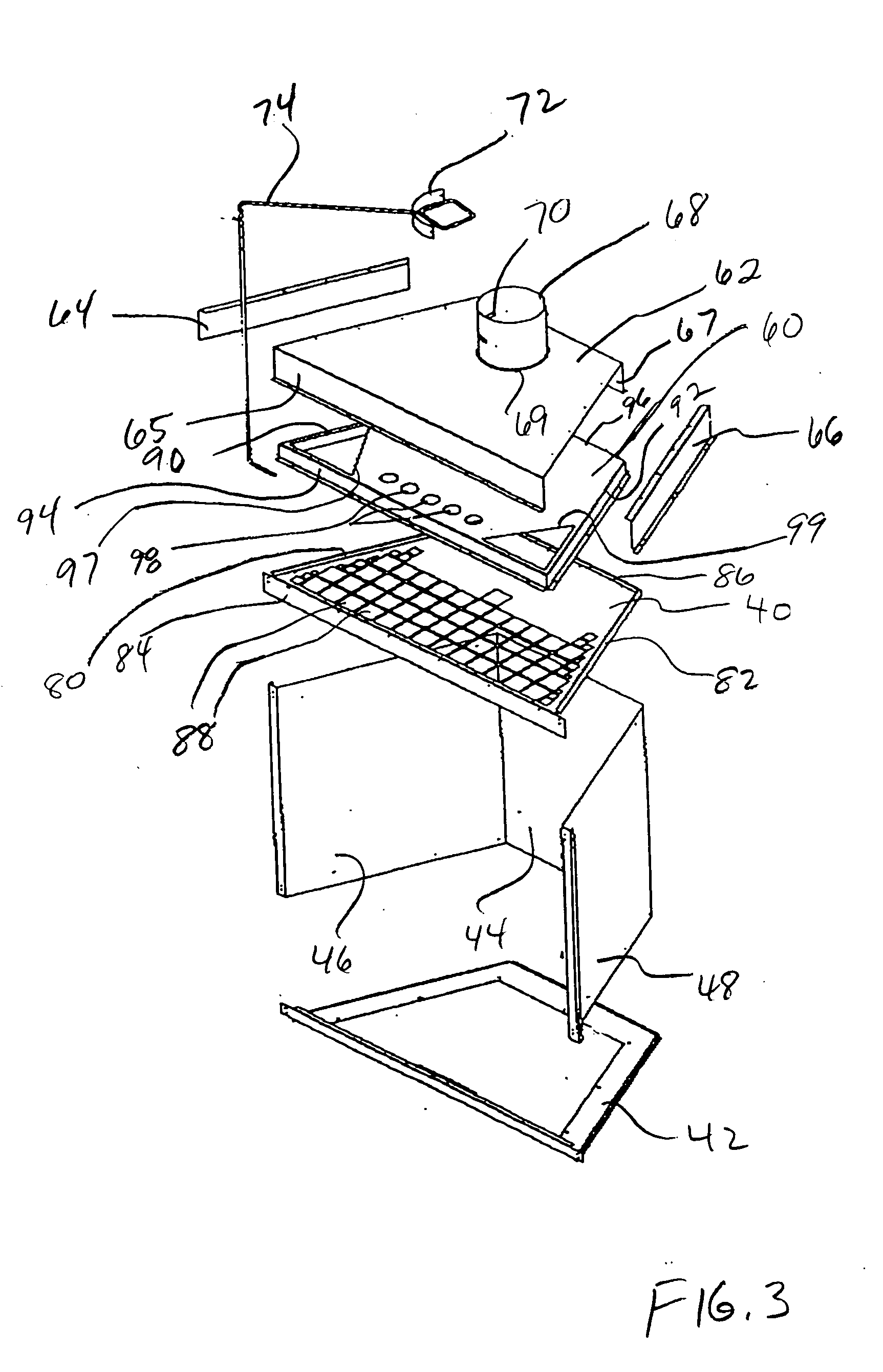
[0022] The present invention generally relates to heating appliances, and more particularly relates to a venting system for a heating appliance. The venting system of the present invention may be useful for venting waste products from an open front combustion chamber, promoting more efficient retention of heat generated by the heating appliance, and providing a safety system to ensure the waste products produced are not released into a living space in proximity to the heating appliance. Although the present invention may be especially useful in a heating appliance with an open front combustion chamber, many principles of the present invention may be applied to heating appliances with a sealed combustion chamber or heating source enclosure.

[0023] As used herein, the term “open front fireplace” refers to any fireplace or heating appliance with an open front for the free flow of room air into the combustion chamber or other heating source enclosure of the appliance. The terms “combust...


PUM


Abstract

A fireplace venting assembly configured to vent a heating source combustion chamber. The venting assembly includes first, second and third panels. The first panel includes a first opening formed therein. The second panel includes a second opening formed therein and is spaced apart from the first panel to define a first venting chamber that is in fluid communication with the combustion chamber. The third panel includes a vent pipe opening formed therein and is spaced apart from the second panel to define a second venting chamber that is in fluid communication with the first venting chamber. The venting assembly also includes a device that is configured to provide a vacuum force at the vent pipe opening to draw air from the combustion chamber through the first and second venting chambers and out the vent pipe opening.

Description

BACKGROUND OF THE INVENTION [0001] 1. Field of the Invention [0002] The present invention generally relates to heating appliances, and more particularly relates to venting systems for heating appliance combustion chambers. [0003] 2. Related Art [0004] Many structures, such as residential, commercial and industrial buildings, include gas and electric appliances, such as furnaces, hot water heaters, clothes dryers, stoves, and fireplaces that produce heated products when gas / air mixtures are combusted or heat is generated. These heated products can contain waste products, such as carbon dioxide, carbon monoxide, excess heat, and / or particulates. For example, a hot water heater produces waste products such as carbon dioxide, carbon monoxide, and excess heat when heating water. An occupant could die if waste products, such as carbon monoxide, reach too high of levels within the structure. In another example, a gas or electric kitchen stove can generate unwanted heat and smoke that must ...

Claims


Application Information

Patent Timeline
Patent Type & Authority Applications(United States)
IPC IPC(8): F24B1/18F24B1/191F24B7/00F24C1/14F24C15/00
CPCF24B1/1808F24C15/001F24B7/005F24B1/191
Inventor MAIELLO, DENNIS R.GROSS, PAUL J.
Owner HNI TECH INC
Why Eureka
Try Eureka