Valve

Inactive Publication Date: 2005-08-04
SCANIA CV AB
View PDF15 Cites 16 Cited by
  • Summary
  • Abstract
  • Description
  • Claims
  • Application Information

AI Technical Summary

Benefits of technology

[0007] The valve comprising the characteristics of the invention provides the advantage of making high flow resolution possible within a desired flow region. Premature failure of the valve after recurrent opening and closing i

Problems solved by technology

This makes it difficult in practice to arrange a flow regulating slit which extends across more than 45 degrees of the shell surface.
A problem with previously known valves is that their flow resolution, i.e. the change in flow per angle unit of rotation of the valve plug, is relatively low, which makes it difficult to set the right flow of hot

Method used


Image

  • Valve
  • Valve
  • Valve

Examples


Example

[0017] The same reference notations throughout are used below for the same characteristics in the various drawings.

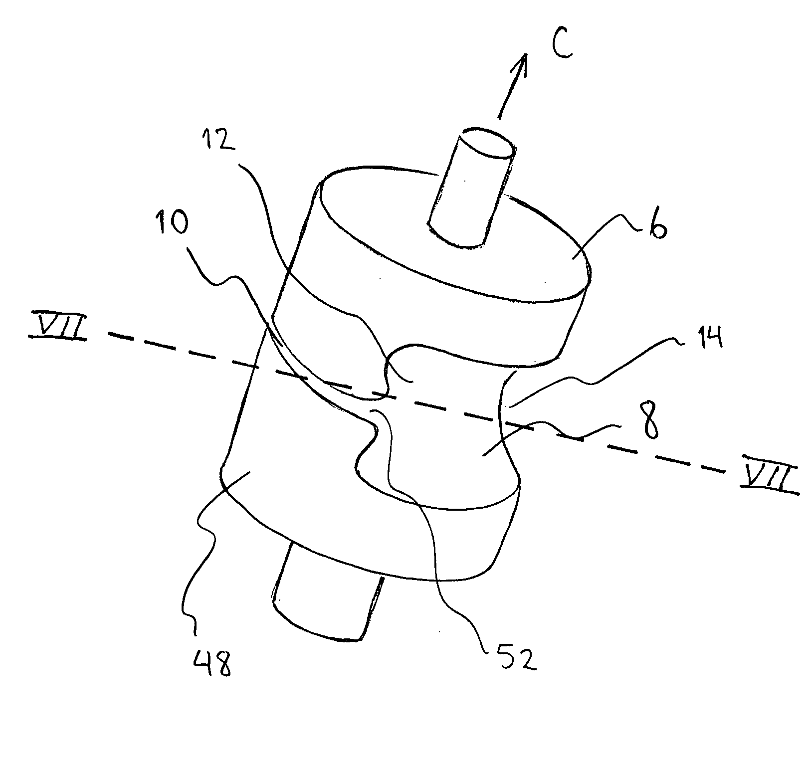
[0018] The present invention relates to a valve 2 with high flow resolution within a flow range, which valve 2 comprises a valve housing 4 and a valve plug 6, whereby the valve plug 6 comprises a cavity 8 and a flow regulating slit 10 which, in cooperation with the valve housing 4, forms a flow passage. On the shell surface 16 of the valve plug 6, when the valve 2 is in a fully open position, there is an area 50 which, relative to the outlet 15 of the valve housing 4, is situated on the other side of the axis of rotation C of the valve plug 6, which area 50 is free from the cavity 8. The intersection of the cavity 8 with the shell surface of the valve plug 6 is preferably situated on the one side of the axis of rotation C of the valve plug 6, e.g. due to the outlet 12 of the cavity 8, when the valve is in a fully open position, being angled relative to the inlet 14 of ...


PUM


Abstract

The invention relates to a valve with high flow resolution within a flow range, which valve comprises a valve housing and a valve plug, whereby the valve plug comprises a cavity and a flow regulating slit which in cooperation with the valve housing forms a flow passage. On the shell surface of the valve plug, when the valve is in a fully open position, there is an area which, relative to the outlet of the valve housing, is situated on the other side of the axis of rotation of the valve plug, which area is free from the cavity. The intersection of the cavity with the shell surface of the valve plug is preferably situated on the one side of the axis of rotation of the valve plug so that the valve plug exhibits a continuous shell surface free from the cavity along at least 180 degrees of the circumference of the valve plug, whereby the flow regulating slit may extend over a substantial portion of the circumference of the valve plug, thereby providing good flow resolution in the flow range in which the flow enters the cavity via the flow regulating slit only.

Description

BACKGROUND OF THE INVENTION [0001] The present invention relates to a valve with high flow resolution within a flow range, which valve comprises a valve housing and a valve plug with a flow regulating slit. [0002] For setting the temperature in a driver's space or passenger space in a vehicle it is possible to use, for example, a rotary valve regulating the flow of hot water through a heat exchanger. The valve may be set either manually or automatically. [0003] In a known valve comprising a valve plug with a flow regulating slit, the valve plug's inlet is arranged centrally relative to the valve plug's outlet and they are connected to one another via a channel which passes through the center of the valve plug, whereby the flow path when the valve is fully open is along a straight line through the valve plug. Turning the valve plug through approximately 90-100 degrees closes the valve. Further turning reopens the valve. In such cases turning the valve from fully open to fully closed ...

Claims


Application Information

Patent Timeline
IPC IPC(8): B60H1/22F16KF16K3/22F16K5/00F16K5/04F16K5/10
CPCF16K5/0407Y10T137/6881
Inventor HALL, OLA
Owner SCANIA CV AB
Why Eureka
Try Eureka