
Actuation system for fluid flow diverter

a technology of fluid flow and actuation system, which is applied in the direction of valves, mechanical equipment, transportation and packaging, etc., can solve the problems of affecting power generation productivity and the environment, the task of fluid diversion devices becoming increasingly difficult, and the need for extensive space for guillotine dampers

Inactive Publication Date: 2005-08-04
BACHMANN INDUSTRIES
View PDF23 Cites 3 Cited by
  • Summary
  • Abstract
  • Description
  • Claims
  • Application Information

AI Technical Summary

Benefits of technology

[0013] The present invention is a flap damper actuation system capable of causing movement of dampers of any size to cause the diversion of a fluid. The damper actuation system is of minimal complexity and may be operated at variable speed selectable as a function of the fluid diversion conditions required.
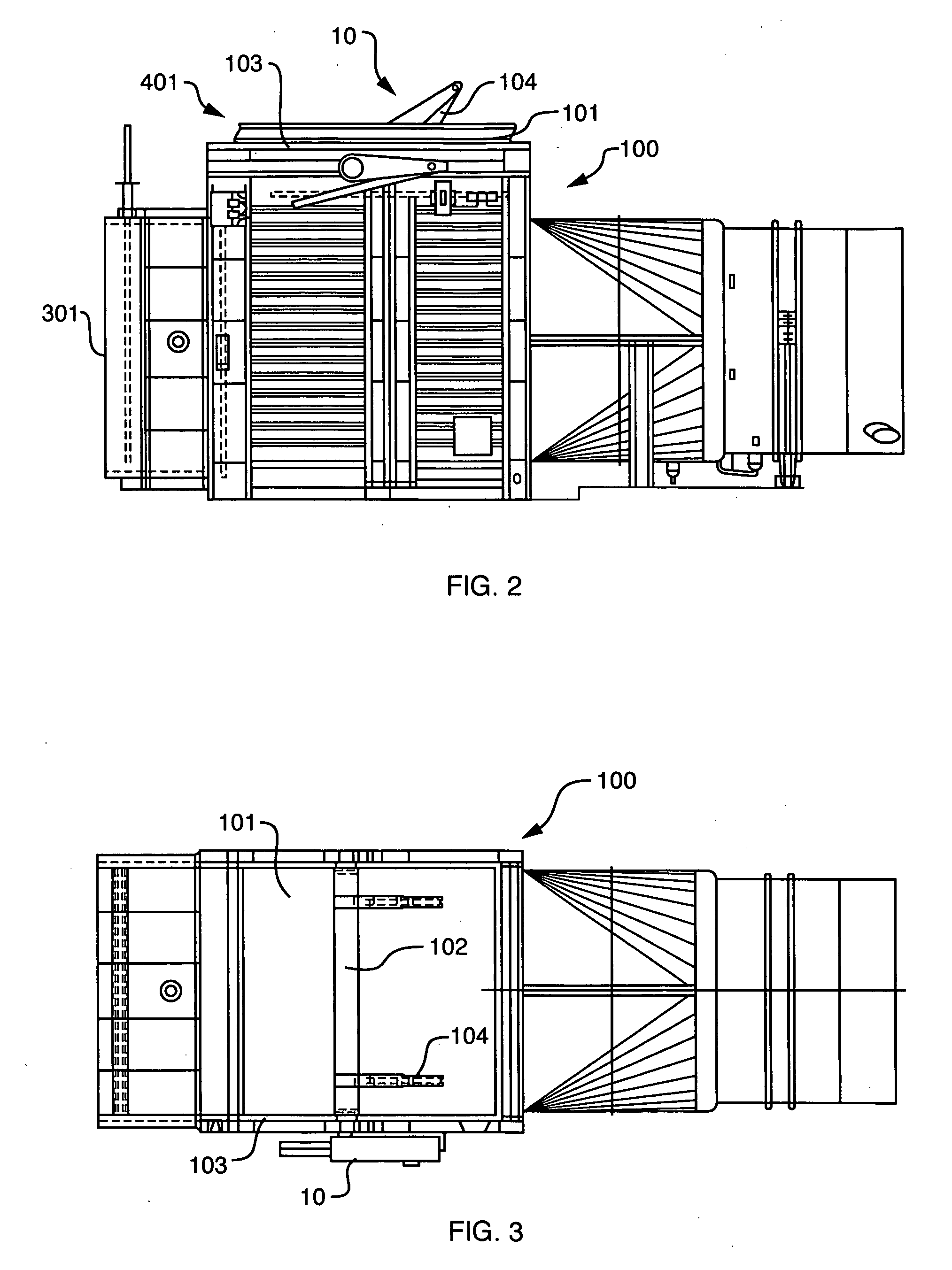
[0014] The damper actuation system is preferably used with a toggle drive arrangement such as is provided with the Bachmann Industries IsoFlap™ damper. The toggle drive includes a toggle tube affixed to the damper flap and coupled to the actuation system. Upon activation of the actuation system, the toggle tube is rotated from a first position to a second position, pivoting the damper flap from a first diversion position to a second diversion position. It is to be understood that the actuation system of the present invention may be employed with other types of structural means for joining the actuator and the damper flap together. However, the toggle tube is a lightweight device having minimal thermal impact while providing suitable structural integrity. The damper actuation system includes a ball screw assembly in combination with a crank arm and a variable frequency drive system to provide an electromechanical device capable of moving damper flaps that have heretofore only been moved by hydraulic actuators.

Problems solved by technology

In the power generation industry in particular, the effective transfer of significant volumes of fluids impacts power generation productivity and the environment.
However, as power generation facilities and systems increase in size, the task of fluid diversion devices becomes increasingly harder.
However, guillotine dampers require extensive space and a substantial support arrangement to allow sufficient blade travel and structural integrity.
Further, the actuation systems associated with guillotine dampers are relatively complex and expensive.
Moreover, because it is completely out of the fluid path when raised, it goes through significant thermal cycling that can result in damper warpage.
Guillotine dampers are therefore not suitable in all circumstances.
On the other hand, because they do remain in the fluid path at all times, they produce substantial pressure drops that reduce operational efficiency.
Further, they are potentially subject to significant contaminant impingement and fouling.
The actuation mechanisms for louver dampers are complex and, in order to reduce excess leakage, supplemental cushion air may be required.
Louver dampers are therefore not suitable in all circumstances.
They are therefore unsuitable in situations where relatively rapid opening or closing is required.
In addition, existing EM actuators are not sufficiently strong to be used in large-scale applications, including in modern power generation systems.
The hydraulic actuators have sufficient strength for use in large systems; however, they are very complex and expensive to install and maintain.

Method used


Image

  • Actuation system for fluid flow diverter
  • Actuation system for fluid flow diverter
  • Actuation system for fluid flow diverter

Examples


Embodiment Construction

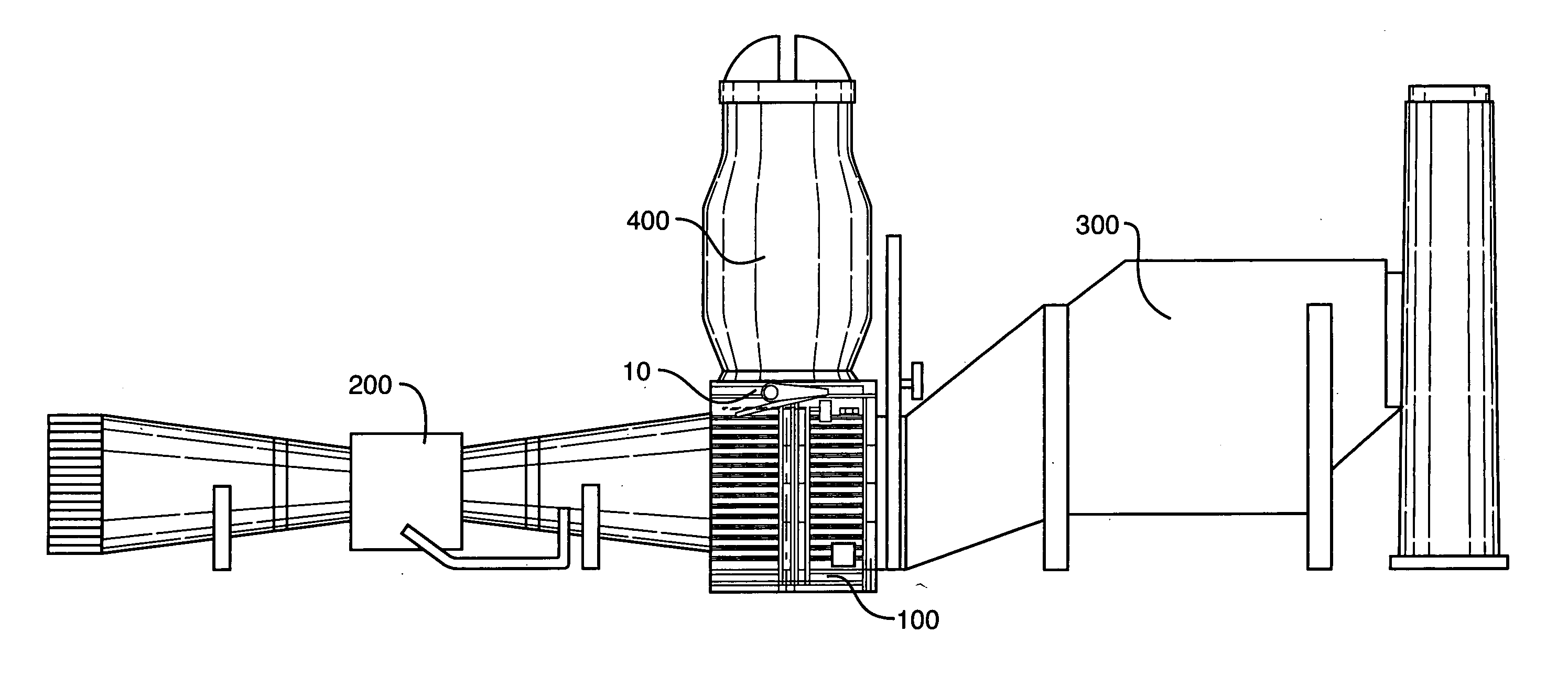
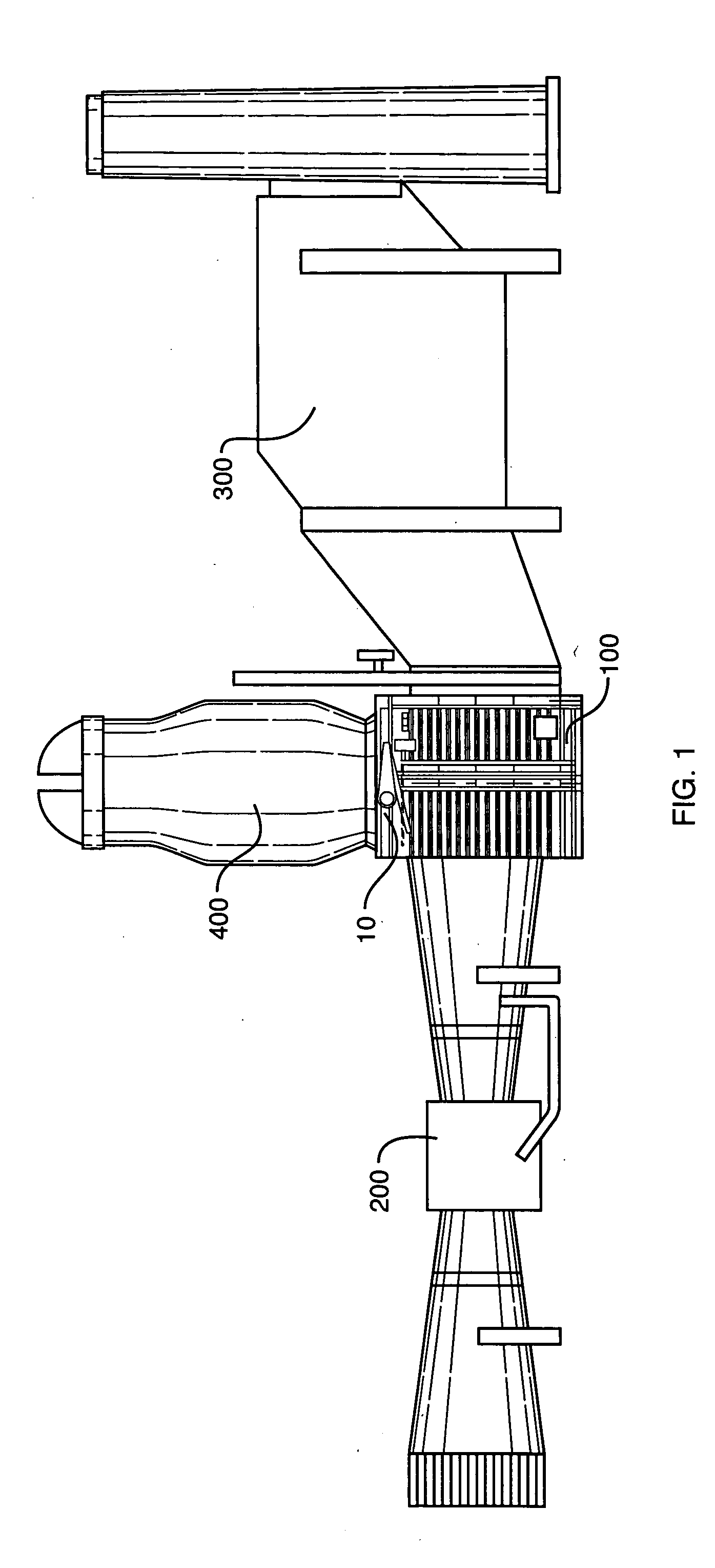
[0043] An actuation system 10 of the present invention is illustrated in the accompanying drawings. The actuation system 10 preferably forms part of a fluid flow diverter 100, such as the fluid flow diverter 100 shown in FIG. 1. The fluid flow diverter 100 of FIG. 1 is part of a fluid flow system of a power generation system including, among other primary components, a turbine 200, a HRSG 300, and an exhaust stack 400. In most cases, the fluid to be diverted is high temperature exhaust gas produced in a combustion container (not shown), is passed through the turbine 200, causing the turbine to move and turn a generator. A portion of the energy associated with the exhaust gas entering the turbine 200 is spent there, but the exhaust gas exiting the turbine may be tapped for additional energy. For that reason, many power generation systems include the HRSG 300 to recover additional energy from the exhaust gas for supplemental power generation. However, the HRSG 300 may not always be us...


PUM


Abstract

An actuation system for causing movement of a fluid flow diverter. The actuation system includes a drive frame assembly, a crank arm assembly and a ball screw assembly working in combination as an electromechanical device suitable for movement of diverter devices of a wide range of sizes. The drive frame assembly is connected to the diverter. The crank arm assembly is attached to the diverter's diverting component, such as a damper flap. The crank arm assembly is connected to the ball screw assembly such that movement of the ball screw forces pivotal movement of the crank arm and, in turn, the diverter's diverting component. A variable speed motor causes linear movement of a ball screw along a fixed rod, with the crank arm assembly connected to the movable ball screw. A drive lockout assembly ensures that movement of the ball screw occurs only under controlled conditions.

Description

BACKGROUND OF THE INVENTION [0001] 1. Field of the Invention [0002] The present invention relates to systems for moving fluids among a plurality of fluid flow pathways. More particularly, the present invention relates to devices for fluid flow diversion in industrial processes, including in power generating systems, but is not limited thereto. Still more particular, the present invention relates to the mechanisms for causing movement of such diversion devices. [0003] 2. Description of the Prior Art [0004] Effective fluid flow transfer is an important aspect of many industrial processes. In the power generation industry in particular, the effective transfer of significant volumes of fluids impacts power generation productivity and the environment. Devices designed to ensure that such fluids move from one portion of the power generation plant to another when desired aid in maximizing productivity and minimizing adverse environmental impact. However, as power generation facilities and ...

Claims


Application Information

Patent Timeline
IPC IPC(8): F16K11/072F16K31/04F16K31/52
CPCF16K31/52F16K31/047Y10T137/87788
Inventor BROTZMAN, JOHN
Owner BACHMANN INDUSTRIES
Learn More