Protector for Electrical Submersible Pumps

a technology for electrical submersible pumps and motor protectors, which is applied in the direction of machines/engines, mechanical equipment, and well accessories, etc., can solve the problems of submersible electric motors that are difficult to protect from corrosive agents and external fluids, and can degrade the dielectric properties of motor oil and insulating materials of motor components

Inactive Publication Date: 2005-08-04
SCHLUMBERGER TECH CORP
View PDF8 Cites 27 Cited by
  • Summary
  • Abstract
  • Description
  • Claims
  • Application Information

AI Technical Summary

Problems solved by technology

These corrosive agents can be detrimental to components of the submersible pumping system, particularly to internal electric motor components, such as copper windings and bronze bearings.
Moreover, irrespective of whether or not the fluid is corrosive, if the fluid enters the motor and mixes with the motor oil, the fluid can degrade the dielectric properties of the motor oil and the insulating materials of the motor components.
Submersible electric motors are difficult to protect from corrosive agents and external fluids because of their design requirements that allow use in the subterranean environment.
As the motor operates, however, heat is generated, which, in turn, heats the internal motor fluid causing expansion of the oil.
In many applications, submersible electric motors are subject to considerable temperature variations due to the subterranean environment, injected fluids, and other internal and external factors.
These temperature variations may cause undesirable fluid expansion and contraction and damage to the motor components.
For example, the high temperatures common to subterranean environments may cause the motor fluid to expand excessively and cause leakage and other mechanical damage to the motor components.
These high temperatures also may destroy or weaken the seals, insulating materials, and other components of the submersible pumping system.
Similarly, undesirable fluid expansion and motor damage can also result from the injection of high-temperature fluids, such as steam, into the submersible pumping system.
As a result, it becomes difficult to prevent the ingress of external fluids into the motor fluid and internal motor components.
These corrosive agents eventually can work their way into the motor oil within the first elastomeric bladder and ultimately corrode and damage internal components of the electric motor.
The wellbore environment also may have an undesirable temperature (e.g., hot), which may destroy the elastomeric bag or bladder and the shaft seal materials throughout the submersible pumping system.
Accordingly, conventional labyrinth type protectors are generally less effective, or totally useless, in orientations deviated from the vertical orientation.

Method used


Image

  • Protector for Electrical Submersible Pumps
  • Protector for Electrical Submersible Pumps
  • Protector for Electrical Submersible Pumps

Examples


Embodiment Construction

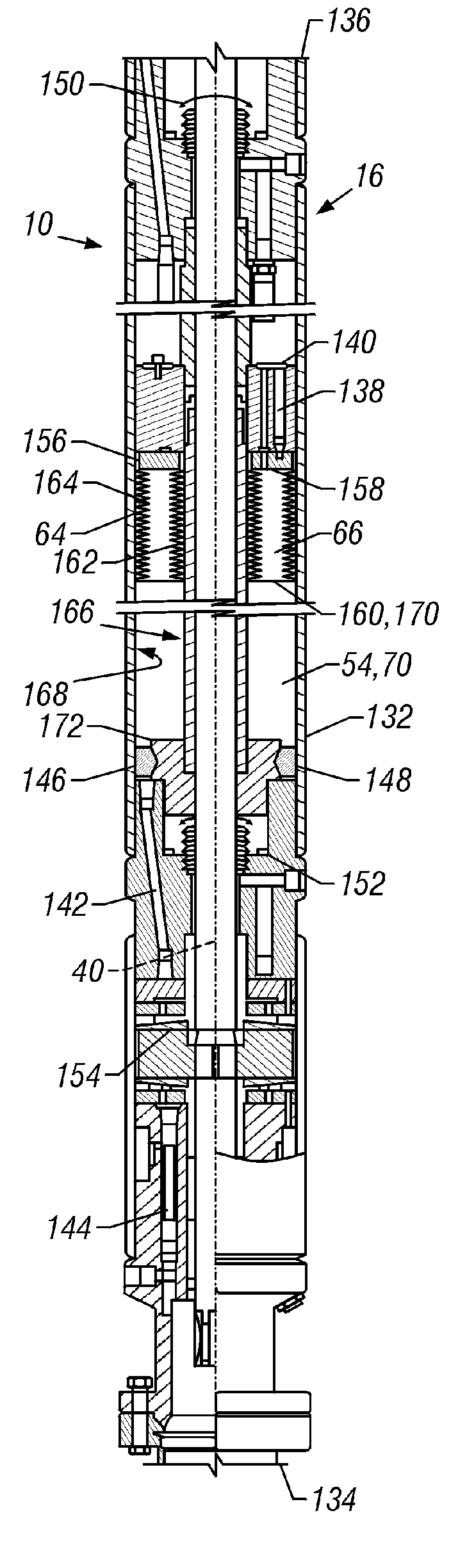
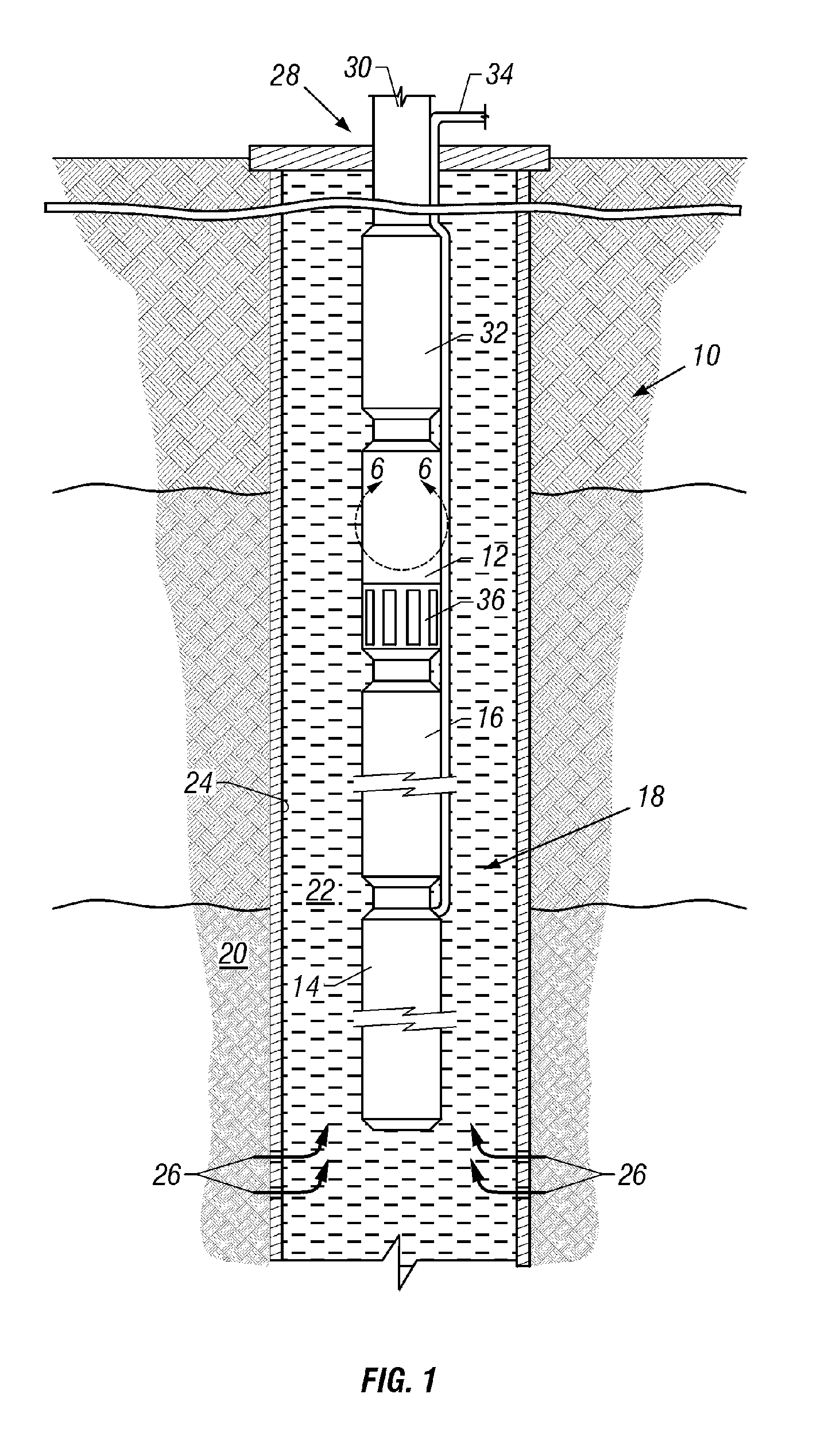
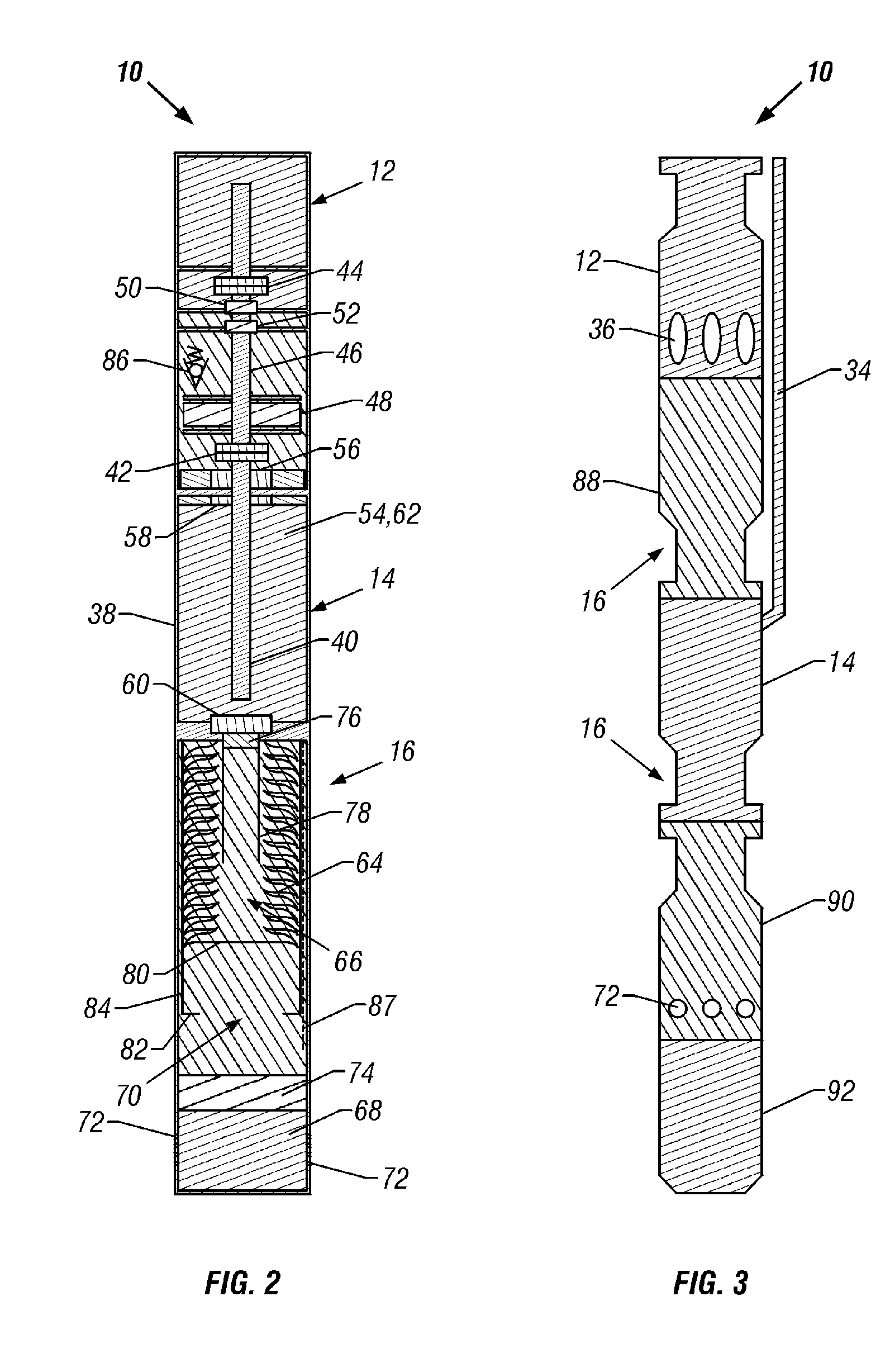
[0037] Referring generally to FIG. 1, an exemplary pumping system 10, such as a submersible pumping system, is illustrated. Pumping system 10 may comprise a variety of components depending on the particular application or environment in which it is used. Typically, system 10 has at least a submersible pump 12, a motor 14 and a motor protector 16. Motor 14 may comprise any electric motor or other motor that requires volume compensation based on, for instance, the thermal expansion and / or contraction of internal fluid. The submersible pump 12 may be of a variety of types, e.g. a centrifugal pump, an axial flow pump, or a mixture thereof. The system 10 may also comprise a gearbox, as is known in the art.

[0038] In the illustrated example, pumping system 10 is designed for deployment in a well 18 within a geological formation 20 containing desirable production fluids, such as petroleum. In a typical application, a wellbore 22 is drilled and lined with a wellbore casing 24. Wellbore casi...


PUM


Abstract

A system and method for protecting a motor for a submersible pumping system. A variety of motor protectors are provided for application in variable temperature environments and multiple wellbore orientations. The motor protectors may include one or more of a positively pressurized bellows, a relatively balanced pressure bellows free of sliding seals, and a multi-orientable labyrinth. Each of these motor protectors also may have various moisture absorbents, filters, particle shedders and various conventional motor protector components.

Description

CROSS REFERENCE TO RELATED APPLICATIONS [0001] This is a continuation of U.S. Ser. No. 10 / 727,922 filed Dec. 4, 2003, which is a divisional of U.S. Ser. No. 10 / 059,795, now U.S. Pat. No. 6,688,860, filed Jan. 29, 2002, which claims the benefit under 35 C.S.C. 119(e) to U.S. Provisional Application No. 60 / 303,860 filed Jul. 9, 2001 and prior Provisional Application No. 60 / 299,013 filed Jun. 18, 2001.FIELD OF THE INVENTION [0002] The present invention relates generally to motor protectors for protecting submersible motors, such as those used in raising fluids from petroleum wells. More particularly, the present invention relates to a motor protection system and method comprising one or both of a protected bellows assembly and a three-dimensional labyrinth assembly. BACKGROUND OF THE INVENTION [0003] A variety of production fluids are pumped from subterranean environments. Different types of submersible pumping systems may be disposed in production fluid deposits at subterranean locati...

Claims


Application Information

Patent Timeline
Patent Type & Authority Applications(United States)
IPC IPC(8): F04D13/06F04D13/10
CPCE21B43/128F04D13/062H02K2205/09F04D15/0077H02K5/132F04D13/10
Inventor DU, MICHAEL H.LEE, LAWRENCE C.ARUMUGAM, ARUNKUMARKISHINO, ASHLEY C.
Owner SCHLUMBERGER TECH CORP
Why Eureka
Try Eureka