Brake drum and process for manufacturing the same

a technology of brake drum and process, which is applied in the direction of brake disc, brake drum, transportation and packaging, etc., can solve the problems of inability to adequately incorporate silicon carbide fine particles into the fins, complicated and troublesome working conditions in the manufacturing process of both the hub b>302/b> and the aluminum alloy disk b>303/b>, and achieves a high compression ratio and high compression ratio. , the effect of increasing strength

Inactive Publication Date: 2005-08-04
NISSIN KOGYO CO LTD +1
View PDF8 Cites 13 Cited by
  • Summary
  • Abstract
  • Description
  • Claims
  • Application Information

AI Technical Summary

Benefits of technology

[0020] The preform having a large thickness in its portion for forming the outer edge of the disk portion of a brake drum and a small thickness in its portion for forming the rest of the brake drum as stated gives a higher compression ratio along its outer edge as compression molded than in the rest. Thus, the preform having a large thickness along its outer edge and a small thickness in the rest thereof and achieving a higher compression ratio along the outer edge than in the rest eventually makes it possible to manufacture a brake drum having an...

Problems solved by technology

The pulley manufacturing process described above requires the separate steps of making two parts, the hub 302 of a composite material and the disk 303 of an aluminum alloy, and its production calls for a great deal of time and labor.
The working conditions in the manufacturing process of both the hub 302 and the aluminum alloy disk 303 are complicated and troublesome.
According to this process for manufacturing a composite material, however, i...

Method used


Image

  • Brake drum and process for manufacturing the same
  • Brake drum and process for manufacturing the same
  • Brake drum and process for manufacturing the same

Examples


Embodiment Construction

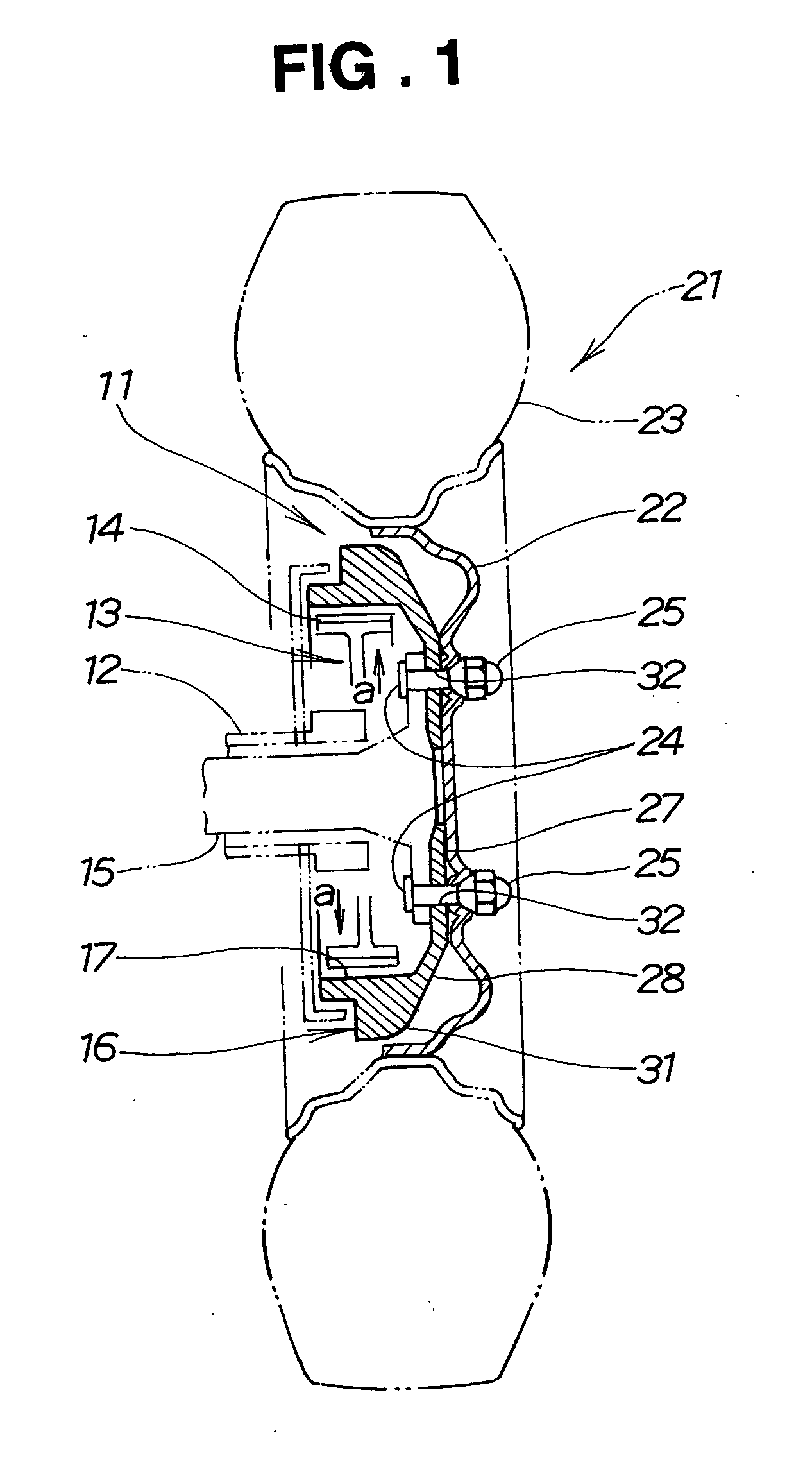
[0032] Referring now to FIG. 1, the drum brake 11 has a brake shoe 13 attached expansibly to an axle tube 12 by a plate not shown and having a lining 14 and a brake drum 16 fixed integrally to a drive or driven axle 15 by a fixing pin not shown and rotatable with the axle 15 and the brake shoe 13 can be pressed in the directions of arrows a against the inner surface 17 of the brake drum 16 to apply friction thereto to stop the rotation of a wheel 21.

[0033] The wheel 21 has a wheel 22 and a tire 23 attached to the wheel 22. The wheel 21 is connected to the axle 15 by a plurality of bolts 24 and a plurality of wheel nuts 25.

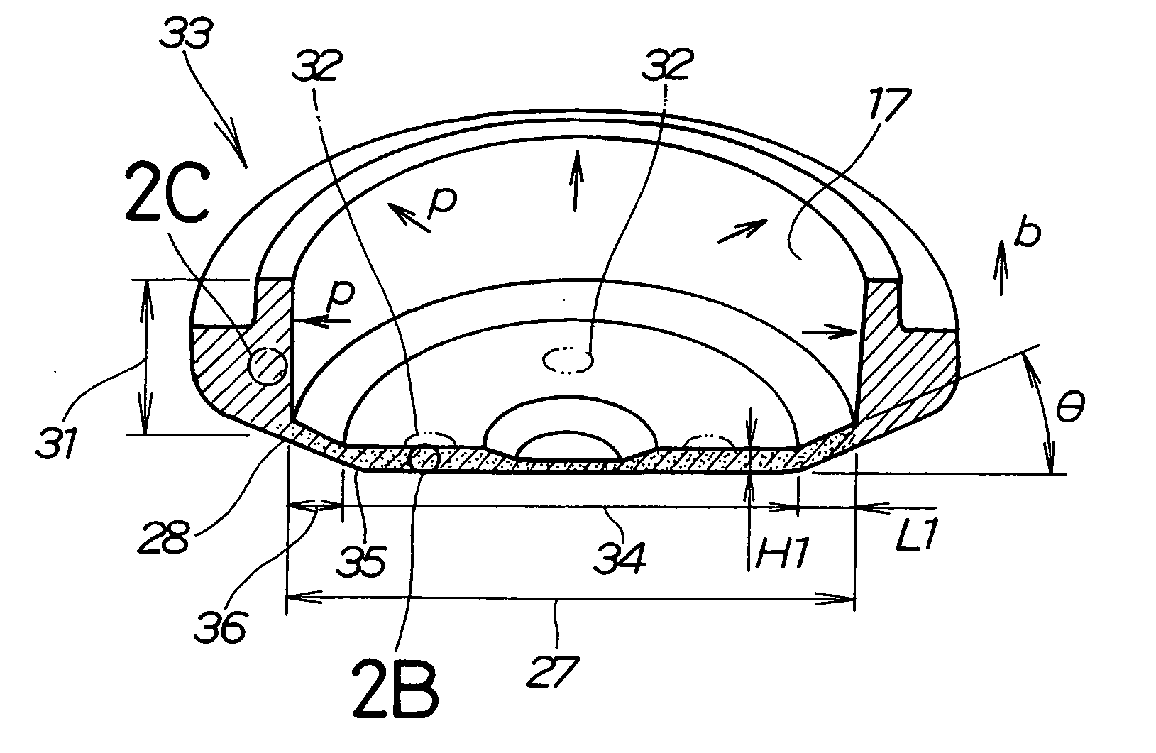
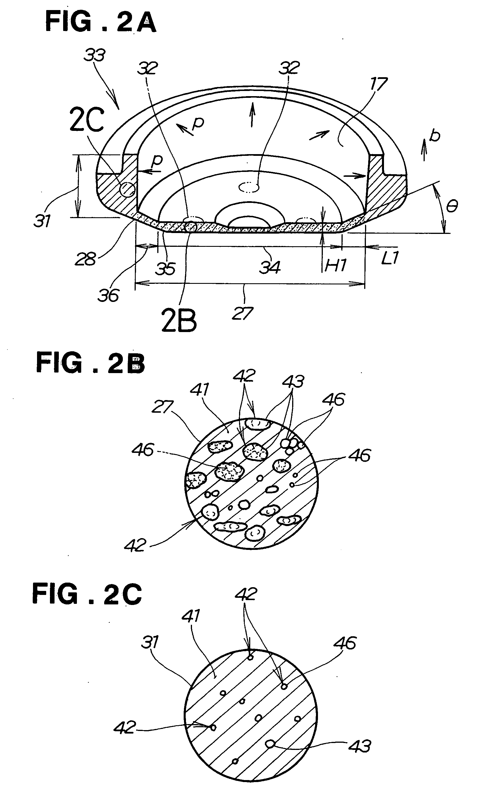
[0034] The brake drum 16 has the shape of a cup defined by a disk portion 27 fixed to the axle 15 and a cylindrical portion 31 protruding from the outer edge 28 of the disk portion 27 in parallel to the axle 15. Its inner surface 17 receives the pressing force of the brake shoe 13. Reference numeral 32 denotes holes made through the disk portion 27 for the bolts ...


PUM

PropertyMeasurementUnit
Thicknessaaaaaaaaaa
Compression ratioaaaaaaaaaa
Contentaaaaaaaaaa

Abstract

A brake drum has its strength elevated in its disk portion. The brake drum is formed from a composition having ceramics dispersed in a matrix. The disk portion has a high ceramic content and thereby a high strength. Its cylindrical portion has a ceramic content decreasing gradually from the outer edge of the disk portion.

Description

FIELD OF THE INVENTION [0001] This invention relates to a brake drum made of a composite material for use in a vehicular brake system and a process for manufacturing such a brake drum. BACKGROUND OF THE INVENTION [0002] It has often been the case in recent years to use an aluminum alloy or an aluminum alloy composite material (MMC) for vehicles to reduce their weight. It is needless to say that a reduction in the weight of the brake system is also important and in an internally expanding type drum brake, for example, there has been sought an art using an aluminum alloy composite material (MMC) for the brake drum rotating with a wheel. [0003] As regards the art using an aluminum alloy composite material (MMC), there is known an art adopting it for pulleys as disclosed in, for example, JP-A-2001-316740. [0004] An art adopting an aluminum alloy composite material (MMC) for heat dissipating members is known from, for example, JP-A-2002-66724. [0005] The process for manufacturing a pulle...

Claims


Application Information

Patent Timeline
IPC IPC(8): F16D65/10F16D65/12
CPCF16D65/12F16D65/125F16D2065/1308F16D2200/0004Y10T29/49998F16D2250/00F16D2250/0023F16D2250/0092F16D2200/0039
Inventor YAMAMOTO, NAOAKIHARUHARA, TSUYOSHIMATSUURA, SATOSHISHOJI, HIROTOECHIGO, TAKAHARUHARA, MASASHITAKANO, HIROKITOYODA, YUSUKEMIZUKAMI, TAKAHIROSHIBATA, KATSUHIRO
Owner NISSIN KOGYO CO LTD
Why Eureka
Try Eureka