Composite helmet for body mount

Inactive Publication Date: 2005-08-04
COOPER STANDARD AUTOMATIVE INC
View PDF23 Cites 3 Cited by
  • Summary
  • Abstract
  • Description
  • Claims
  • Application Information

AI Technical Summary

Benefits of technology

[0016] A primary advantage of the invention resides in reduction in mass of the assembly.
[0017] Still another advantage of the invention is the ability to eliminate any anti-corrosion coating.
[0018] Still another advantage resides in the temporary bolt retention feature to simplify assembly.

Problems solved by technology

This is a tooling intensive process and requires the designer to provide sufficient material thickness to achieve suitable crush loads.
The deep-drawn helmet is generally b

Method used


Image

  • Composite helmet for body mount
  • Composite helmet for body mount
  • Composite helmet for body mount

Examples


Example

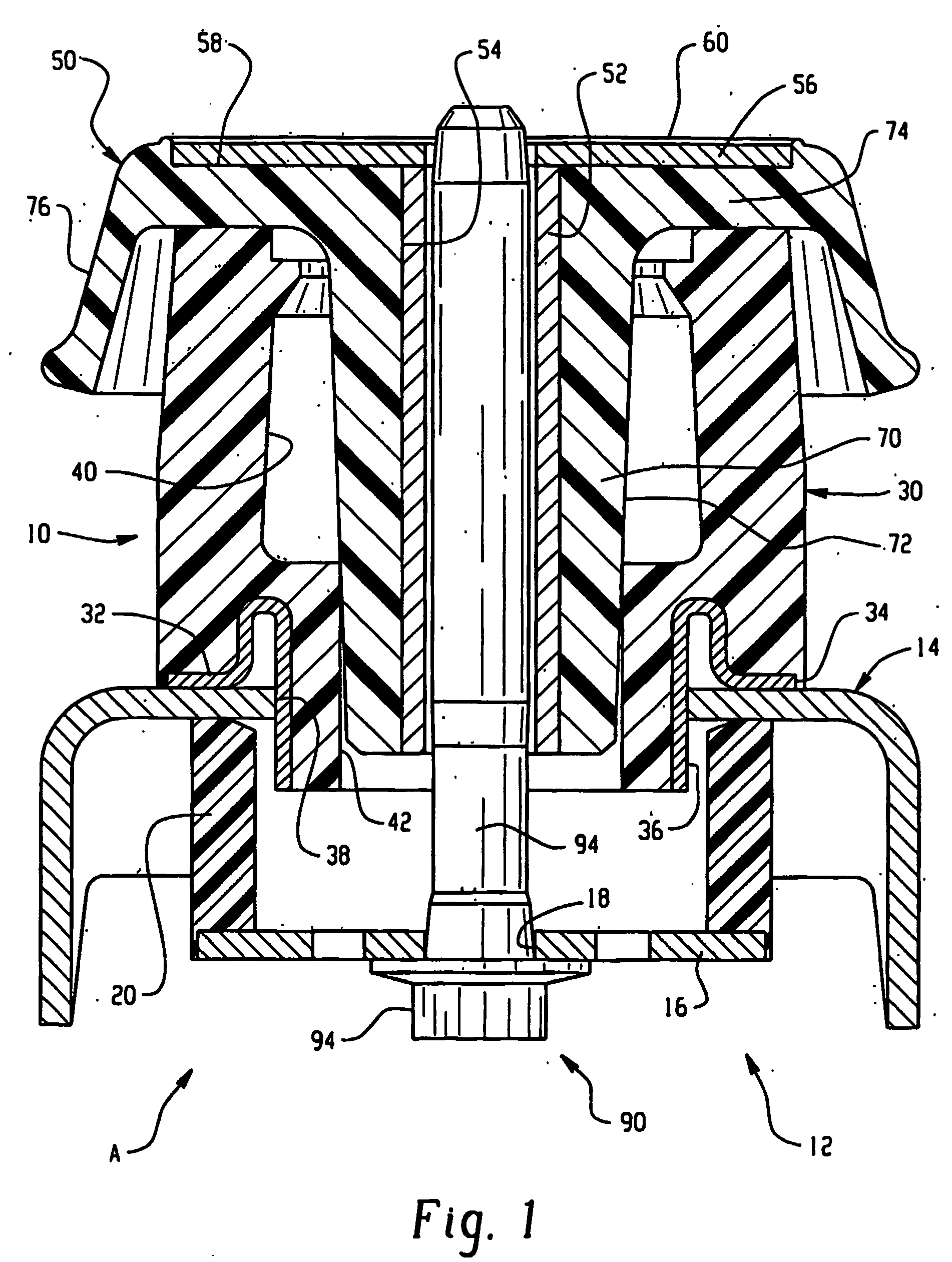
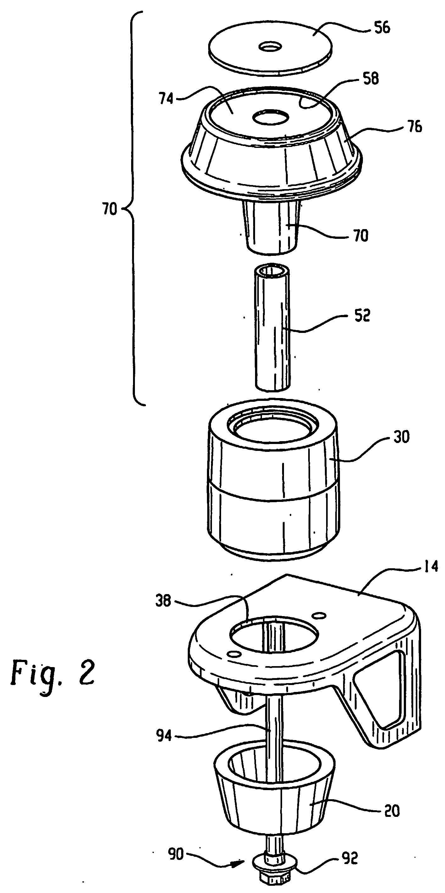
[0025] Turning initially to FIG. 1, the assembled body mount assembly A is illustrated. It includes a first or upper body mount portion 10 and a second or lower body mount portion 12 disposed on opposite sides of a vehicle frame 14. The lower body mount portion, also referred to as a rebound cushion assembly, includes a metal clamp disk 16 having a central opening 18 for mounting purposes. The metal clamp disk abuttingly engages cushion member 20, preferably an elastomeric material that provides desired energy damping or vibration attenuation. As shown here, the lower cushion member is a generally cylindrical structure that abuts a surface of the frame at a first or upper end 22 and may include a recess at a second or lower end 24 for receipt of or abutting engagement with the metal disk. Of course, one skilled in the art will appreciate the lower cushion member may adopt a wide variety of configurations as may be required for a particular design. For example, the lower cushion may ...


PUM


Abstract

A composite helmet is provided for a body mount. The helmet includes an interior structural load bearing skeleton including an elongated cylinder, and a disk or washer mold-bonded with the polymeric or elastomeric portion of the helmet. The elastomeric portion of the helmet includes an elongated axial portion that encompasses the metal cylinder and an over-mold layer, if desired, over the metal disk. In some instances, a ring is incorporated into the shroud for increased strength and rigidity.

Description

[0001] This application claims the priority benefit of and hereby expressly incorporates by reference U.S. provisional application Ser. No. 60 / 354,161, filed Feb. 4, 2002.BACKGROUND OF THE INVENTION [0002] The present invention is directed to a body mount or cushion assembly for an automotive vehicle or truck. More particularly, the present invention is directed to a body mount assembly used to insulate or cushion vibration and shock between the frame and vehicle components. [0003] Body on frame vehicles, including trucks, typically include body mounts disposed between the vehicle components and the frame to provide cushioning therebetween. The body mount typically includes a shock absorbing or vibration absorbing material (a cushioning assembly) such as an elastomeric member and a shell or helmet formed of sheet metal that overlies or enshrouds the elastomeric member. The helmet is typically constructed as a single piece of deep-drawn steel. This is a tooling intensive process and ...

Claims


Application Information

Patent Timeline
IPC IPC(8): B29CF16F15/08B62D23/00B62D24/02B62D24/04F16F1/373F16F1/40F16F3/087F16F9/00F16F9/36F16F9/38
CPCF16F3/0873F16F1/3735B62D24/02F16F7/12
Inventor NICHOLLS, KEVIN
Owner COOPER STANDARD AUTOMATIVE INC
Why Eureka
Try Eureka