Process and apparatus for joining components using laser radiation

a technology of laser radiation and components, applied in the direction of laser beam welding apparatus, welding apparatus, manufacturing tools, etc., to achieve the effect of widening the range of applications of the scanner process

Inactive Publication Date: 2005-08-04
LEISTER PROCESS TECH
View PDF3 Cites 15 Cited by
  • Summary
  • Abstract
  • Description
  • Claims
  • Application Information

AI Technical Summary

Benefits of technology

[0005] Therefore, the present invention is based on the object of proposing a possible way of compensating for the shadow effect resulting from the beam angle in order to widen the range of applications of the scanner process.
[0007] According to the invention, this is achieved by virtue of the fact that an additional diverter device is arranged between the illumination device and the components, and the laser beam which has been diverted onto the diverter device from the illumination device is diverted toward locations at the components which cannot be reached directly from the illumination device. This makes it possible to avoid shadow effects and to achieve favorable heating angles with the minimum possible energy. The diversion may also be effected by reflective, substantially stationary surfaces or also, for example, by moving mirrors, micro-optical components, micro-optically structured foils. These may be integrated in a pressing-together device or may also be arranged outside it.

Problems solved by technology

This process causes problems if large-volume parts or complicated parts are to be welded to one another, these parts, by way of example, additionally having a flange for the welding, along which the two components are to be welded to one another.
Corresponding problems also occur when soldering the connections of relatively large electronic components, in which the connections are not directly accessible to the laser beam.

Method used


Image

  • Process and apparatus for joining components using laser radiation
  • Process and apparatus for joining components using laser radiation
  • Process and apparatus for joining components using laser radiation

Examples


Embodiment Construction

)

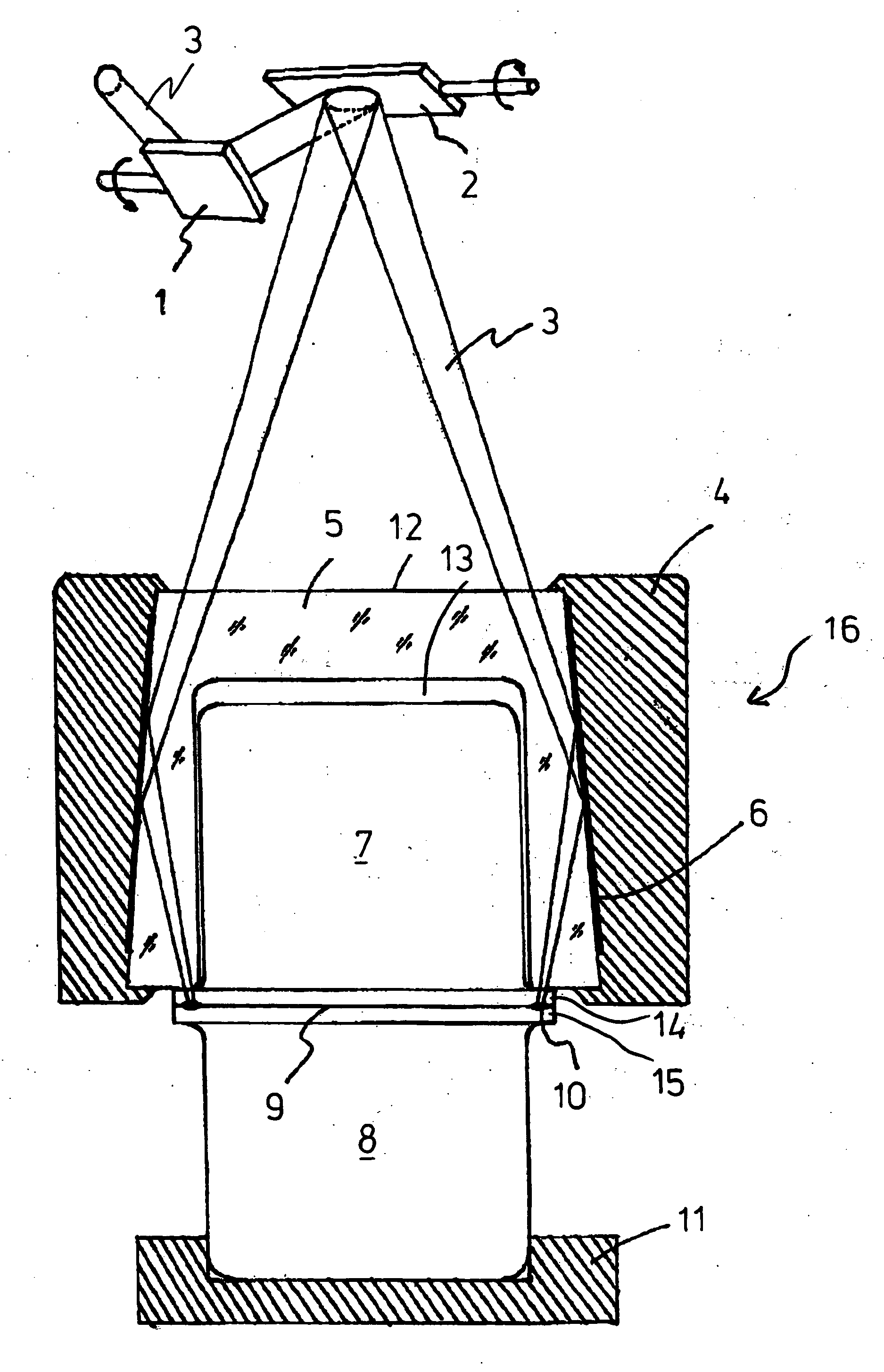
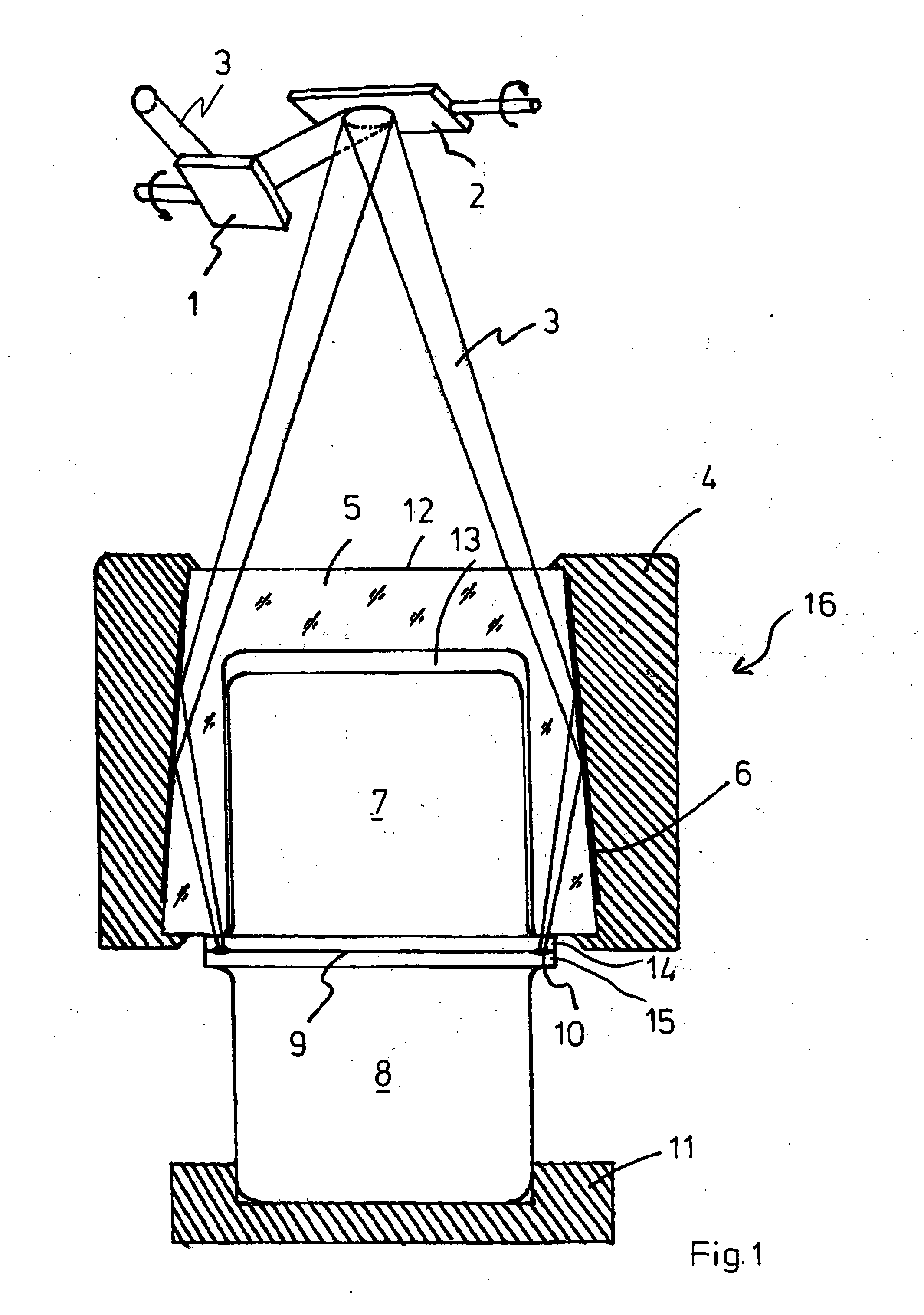
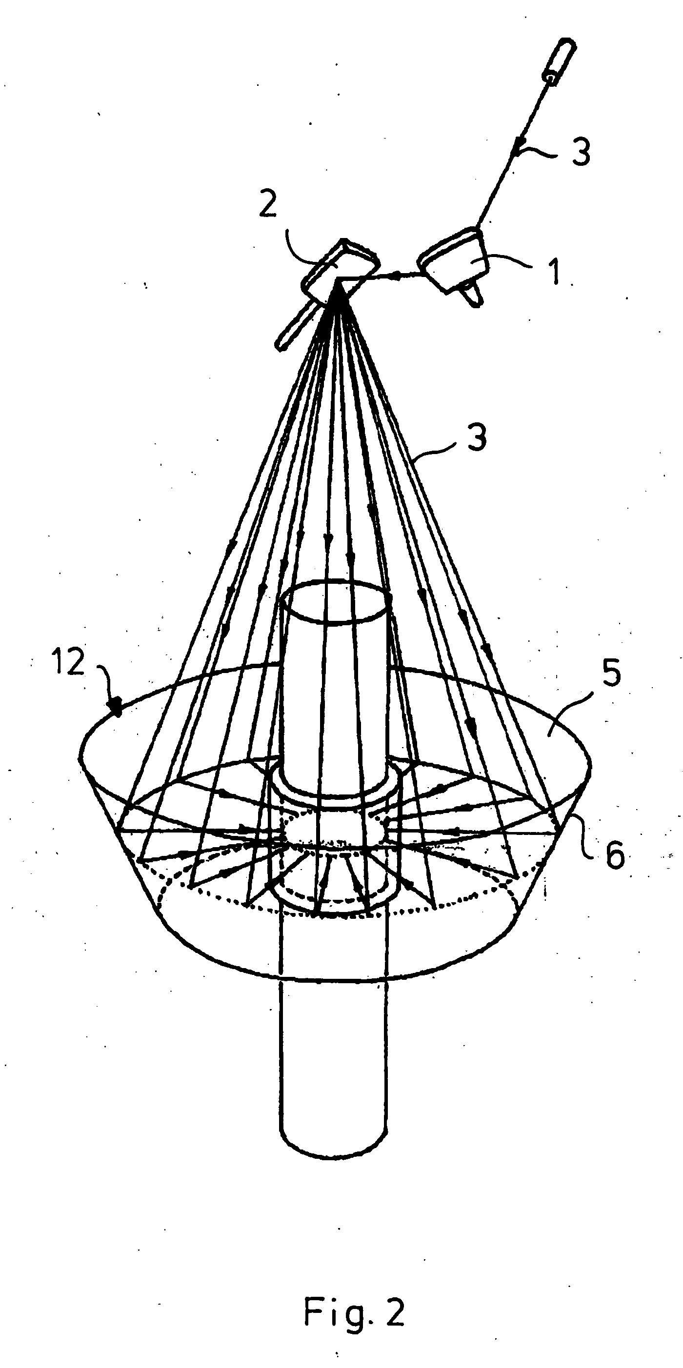
[0014] In accordance with FIG. 1, via a first scanner mirror 1, which can rotate about an axis, and a second scanner mirror 2, which can rotate about an axis, the laser beam 3, which impinges on these scanner mirrors 1, 2 in suitable form (this arrangement overall forming the illumination device), in this example in round form, is diverted toward the components 7 and 8 which are to be joined to one another. The components 7 and 8 are held in a clamping device which comprises an upper holding element, in the form of the metallic clamping frame 4, and a lower holding plate 11. The metallic clamping frame 4 holds a clamping part 5 which is transparent to the laser radiation and is designed to match the overall shape of the upper component 7. For this purpose, it has a suitable receiving cavity 13, in which there is space for the component 7 and which is designed in such a way that it is supported on the flange 14. Accordingly, in the exemplary embodiment the lower component 8 has an a...


PUM

PropertyMeasurementUnit
transparentaaaaaaaaaa
shapeaaaaaaaaaa
pressureaaaaaaaaaa

Abstract

Process and apparatus for joining components, in particular plastic components, by laser beams using a transmission welding process. To ensure that the laser beams are simultaneously introduced into the region of the joint seam even in the case of relatively large components, a clamping element is provided. The clamping element includes devices for diverting the laser beam onto the joint seam. In addition, there is a clamping part which is matched to the shape of the components and is transparent to the laser beam, by which clamping part the components are pressed together and the laser beam is introduced into the region of the joint seam. This allows a scanner process to be used without restriction for all possible components in particular in the case of simultaneous welding. The process can also be used to solder connections for electronic components.

Description

BACKGROUND OF THE INVENTION [0001] Process for joining components, in particular plastic components, or also for soldering connections of electronic components, by means of laser beams, in which a laser beam is generated and is diverted from an illumination device, quasi-simultaneously, onto the locations that are to be joined, in accordance with the joining contour. The invention also relates to an apparatus for joining components, in particular plastic components, by laser beams by means of a laser source and an illumination device for the shaping and targeted diversion the laser beam quasi-simultaneously, onto the locations that are to be joined, and a pressing-together device for the components at least in the region that is to be joined. [0002] The joining of plastic components by means of laser beams in the IR region, in particular, using the transmission welding process, is generally known. In this process, the components are joined to one another in such a manner that a firs...

Claims


Application Information

Patent Timeline
Patent Type & Authority Applications(United States)
IPC IPC(8): B23K26/08B23K26/10B23K26/00B23K26/28B23K26/32B29C35/08B29C65/16
CPCB23K26/0807B29C66/54B23K26/285B29C65/1635B29C65/1654B29C65/1661B29C65/1687B29C66/1122B29C66/1312B29C66/5221B29C66/81267B29C2035/0822B29C65/7841B29C66/542B29C66/8322B23K26/10B23K26/082B23K26/282B29K2995/0027B29C66/81268
Inventor CHEN, JIE-WEILEISTER, CHRISTIANE
Owner LEISTER PROCESS TECH
Why Eureka
Try Eureka