
Method for manufacturing honeycomb structure

a technology of honeycomb and structure, applied in the direction of machines/engines, drying solid materials, drying machines, etc., can solve the problems of cross sectional deformation distortion and twisting of the formed body, and difficulty in joining the segments to each other, so as to reduce distortion and cross sectional deformation.

Active Publication Date: 2005-08-04
NGK INSULATORS LTD
View PDF0 Cites 9 Cited by
  • Summary
  • Abstract
  • Description
  • Claims
  • Application Information

AI Technical Summary

Benefits of technology

[0006] The present invention has been made in view of such a situation, and aims at providing a method for manufacturing a honeycomb structure which can reduce distortion and cross sectional deformation of a finished honeycomb structure by reducing them in a forming step or a drying step of the method.

Problems solved by technology

In the forming step and the drying step in such a producing method, deformation such as distortion and a twist of the formed body occurs.
In such cases, it is difficult to join the segments to each other when deformation such as distortion and twists occur in the respective segments.
In these methods, though the distortion of the formed body can be inhibited, cells may be collapsed in some cases, which may result in cross sectional deformation of the formed body.

Method used


Image

  • Method for manufacturing honeycomb structure
  • Method for manufacturing honeycomb structure
  • Method for manufacturing honeycomb structure

Examples


Embodiment Construction

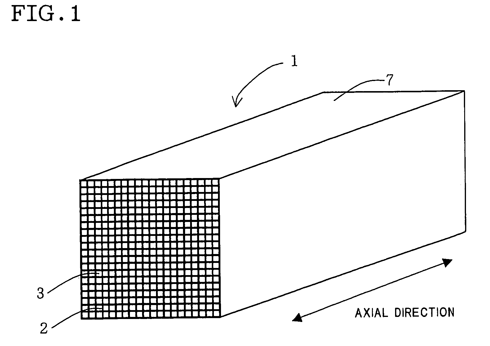
[0021] Methods for manufacturing a honeycomb structure according to the first to third aspects of the present invention are described below in detail with reference to the concrete embodiments. However, the present invention is not restricted to the following embodiments. Incidentally, in the present description, the expression “section” means a section perpendicular to the axial direction shown in FIG. 1, unless otherwise specified.

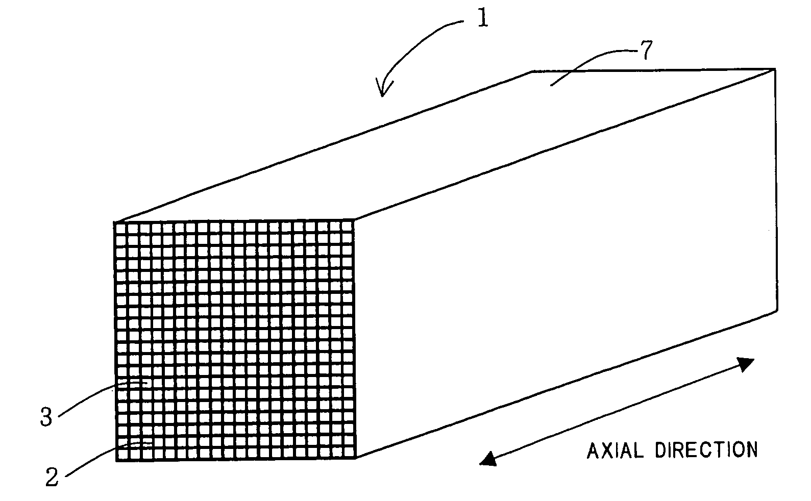
[0022] A forming step according to the first to third aspects of the present invention is a step of forming, by extrusion, a formed body 1 having an outer wall 7, partition walls 2 provided inside the outer wall 7, and cells 3 each surrounded by the partition walls 2 as well as extending to an axial direction of the body, for example, as shown in FIG. 1. A drying step is a step of drying the formed body 1 being extruded to remove moisture.

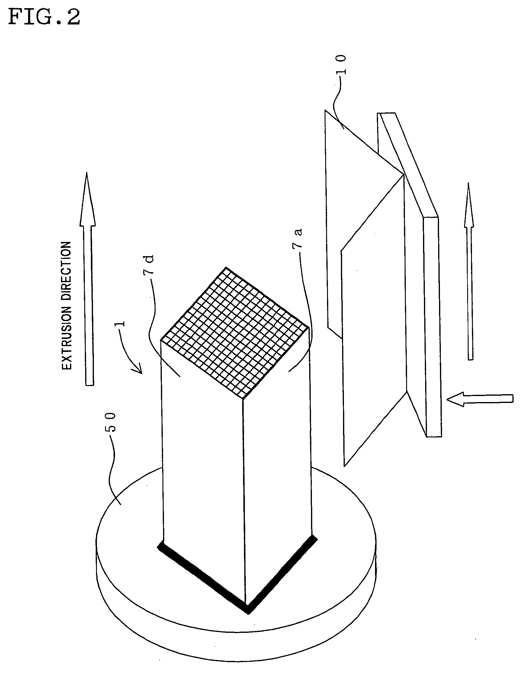
[0023] Important characteristics of the first aspect are as follows. As shown in FIGS. 2 and 3, the forming step in...


PUM

PropertyMeasurementUnit
angleaaaaaaaaaa
angleaaaaaaaaaa
angleaaaaaaaaaa

Abstract

The present invention provides a method for manufacturing a honeycomb structure, the method including steps of: forming, by extrusion, a formed body 1 having an outer wall, partition walls provided inside the outer wall, and cells each surrounded by the partition walls as well as extending to an axial direction of the body; and drying the formed body 1. The method for manufacturing the honeycomb structure is characterized in that the forming step includes receiving the formed body on a cradle 10 which receives the formed body so that an angle of a face 7a of the outer wall on the cradle 10 relative to the horizontal plane is 15 to 35 degrees, a cradle which has a V-shaped cross section with a cut at an apex of the V shape and which receives the formed body so that the angle relative to the horizontal plane is 15 to 45 degrees, or a cradle which receives one face of the formed body and characterized in that the drying step includes drying the formed body 1 in a state of being received on the cradle 10 having the predetermined angle. The method for manufacturing the honeycomb structure reduces distortion and deformation of the honeycomb structure.

Description

TECHNICAL FIELD [0001] The present invention relates to a method for manufacturing a honeycomb structure. Particularly, the present invention relates to a method for manufacturing a honeycomb structure, which can inhibit distortion and cross sectional deformation of a honeycomb structure in a forming step or a drying step of the method. BACKGROUND ART [0002] A honeycomb structure is widely used for catalyst carriers and various filters. Recently, the honeycomb structure gets attention as a filter for trapping particulate matter exhausted from diesel engine (hereinafter referred to as DPF). [0003] Such a honeycomb structure generally contains ceramics as a main component in many cases. Following method is generally taken for producing the honeycomb structure. After adding several kinds of additives to the ceramic raw material to form clay, the clay is extruded to form honeycomb formed body, then the formed body is dried and fired to obtain the honeycomb structure. [0004] In the formi...

Claims


Application Information

Patent Timeline
Patent Type & Authority Applications(United States)
IPC IPC(8): F01N3/02B01D39/00B01D39/20B01J35/04B28B3/20B28B11/24B28B17/00B29C48/11B29C48/32F26B3/34F26B25/18
CPCB28B3/269B28B11/241B28B11/243B28B11/248B28B17/00F26B2210/02B29C47/0028B29C47/12B29L2031/60F26B3/343F26B25/18B28B2003/203B29C48/11B29C48/355B29C48/345B28B3/20
Inventor NATE, MASAYUKIKANEKO, TAKAHISAWADA, YUKIHISA
Owner NGK INSULATORS LTD
Learn More