Vented end cap with integrated splash shield for permanent magnet DC motor

Active Publication Date: 2005-08-04
BROSE FAHRZEUGTEILE GMBH & CO KG HALLSTADT (DE)
View PDF20 Cites 14 Cited by
  • Summary
  • Abstract
  • Description
  • Claims
  • Application Information

AI Technical Summary

Benefits of technology

[0010] Other objects, features and characteristics of the present invention, as well as the methods of operation and the functions of the related elements of the structure, the combination of parts and economics

Problems solved by technology

The conventional vented motor configuration may not fulfill muddy-water spray test requirements stipulated by some auto manufacturers.
An excessive amount of mud can enter the motor through the holes 12 and can eventually form a very abrasive and poor conductive layer on the top of the commutator bars.
Furthermore, solidified mud can seize the brush in the

Method used


Image

  • Vented end cap with integrated splash shield for permanent magnet DC motor
  • Vented end cap with integrated splash shield for permanent magnet DC motor
  • Vented end cap with integrated splash shield for permanent magnet DC motor

Examples


Embodiment Construction

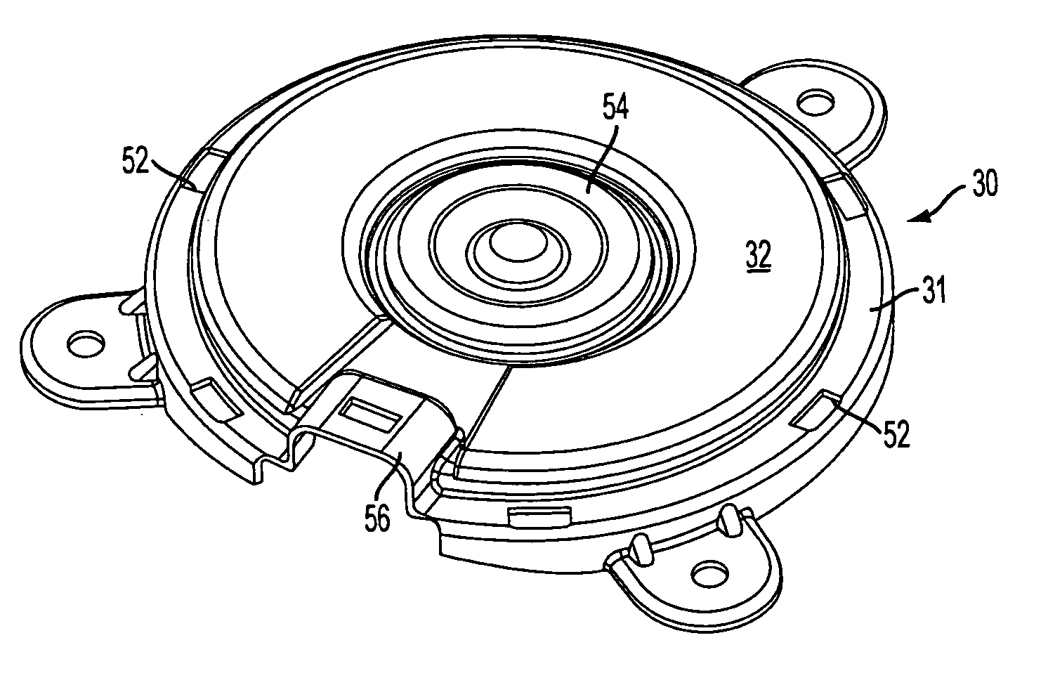
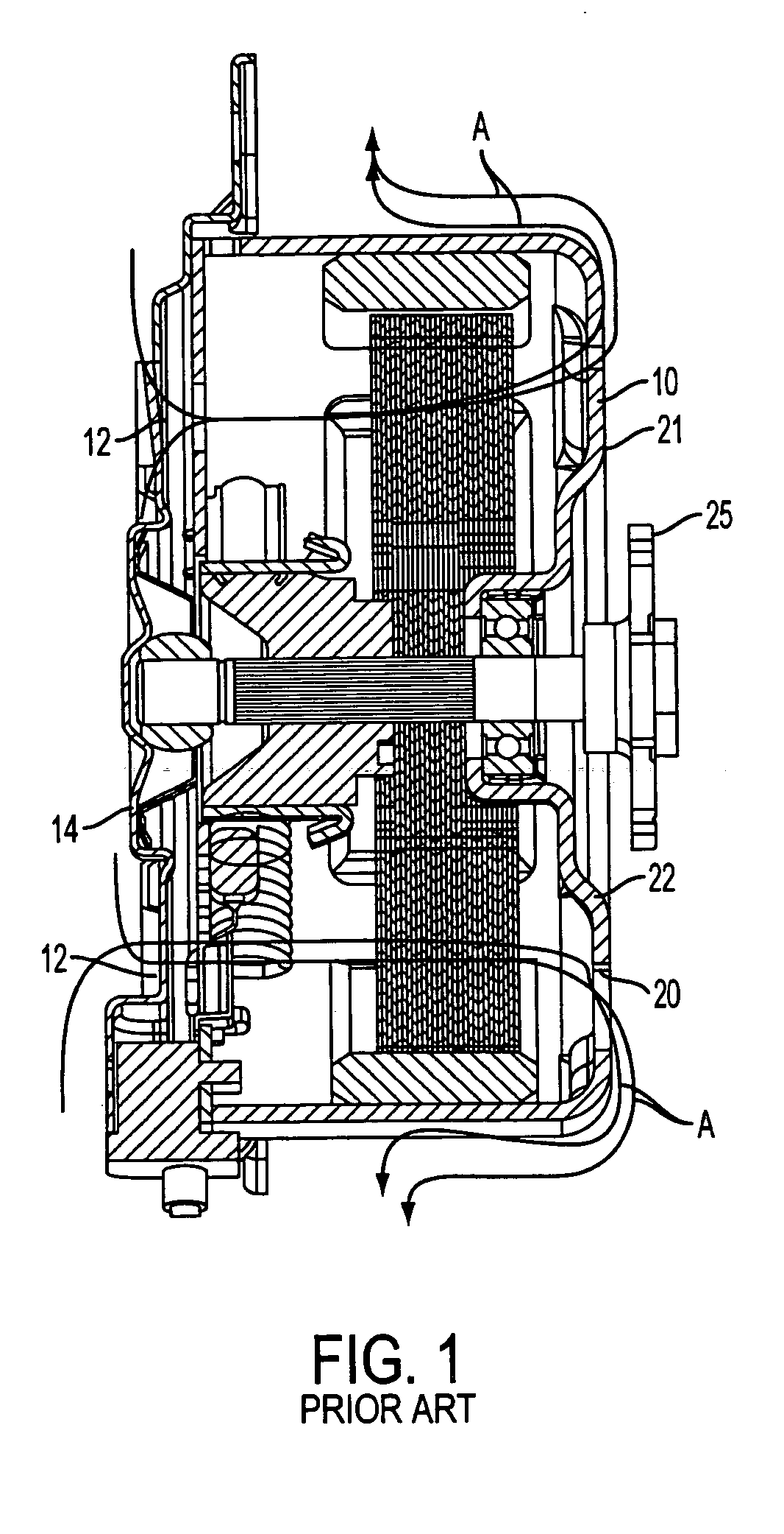
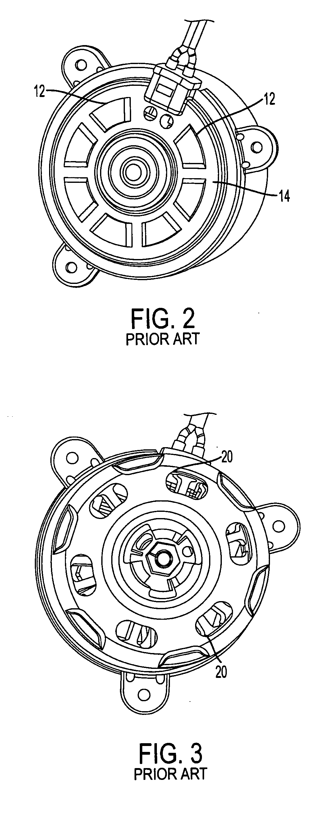
[0019] With reference to FIGS. 5-7 an end cap with integrated splash shield assembly is shown generally indicated at 30. The assembly 30 includes a vented end cap 31, covering or closing a first, opened end 27 of a housing 29 of a motor 36, and an integrated splash shield 32. The housing 29 of the permanent magnet DC motor 36 has a substantially closed second end, considered the stator end 42 and a shaft 35 mounted for rotation extending from the stator end 42. The stator end 42 can be considered to be identical to that of FIG. 1, having vent holes 20 therein for venting the motor.

[0020] A bearing (not shown) under the end cap 31 supports an end 33 of a shaft 35 of the motor 36. The other end of the shaft 35 includes an adapter plate 25 for mounting a fan hub 16 (FIG. 4) thereto. As in the embodiment of FIG. 1, in the embodiment of FIG. 7, low pressure created by the fins 18 of the fan hub 16, when mounted to the adapter plate 25, causes air to flown into the venting holes 34 in th...


PUM


Abstract

A permanent magnet D.C. electric motor 36 includes a motor housing 29 having first and second ends. The second end 42 is substantially closed and has an end of a shaft 35 extending there from. The second end includes vent holes 20 therein. The first end 27 is substantially open. An end cap 31 closes the first end of the housing. The end cap 31 has venting holes 34 therein for permitting air to pass there-through to cool the motor. A splash shield 32 is integral with the end cap 31 and covers the venting holes 34 in such a manner to limit foreign matter from entering the venting holes while permitting air to flow through the venting holes.

Description

[0001] This applicant is based on U.S. Provisional Application No. 60 / 540,117, filed on Jan. 29, 2004 and claims the benefit thereof for priority purposes.FIELD OF THE INVENTION [0002] This invention relates to permanent magnet DC motors and, more particularly, to a vented end cap of a motor having an integrated splash shield. BACKGROUND OF THE INVENTION [0003] With reference to FIG. 1, ventilation of a conventional engine cooling permanent magnet DC brush motor 10 is shown. The airflow path through the motor 10 is indicated by the curved lines A. Air is drawn through the motor 10 via venting holes 12 (FIG. 2) in the end cap 14. A fan hub 16 with fins 18 (FIG. 4) creates a low pressure region at the stator end 21 such that hot air from the motor 10 is drawn out through vent holes 20 in the stator 22 (FIG. 3). Although not shown in FIG. 1, it can be appreciated that the hub 16 is mounted to the fan adaptor plate 25 and provides some splash protection to holes 20. [0004] The conventio...

Claims


Application Information

Patent Timeline
IPC IPC(8): H02K5/20H02K9/06
CPCH02K9/06H02K5/20H02K5/207
Inventor SIMOFI-ILYES, ATTILAMUGAN, SHANLAKERDAS, ANDREW
Owner BROSE FAHRZEUGTEILE GMBH & CO KG HALLSTADT (DE)
Why Eureka
Try Eureka