
Solid state image pick-up device and image pick-up system

a solid-state image and pickup device technology, applied in the field of solid-state image pickup, can solve the problems of mos type sensor noise reduction, large electrical power consumption, and small noise amount, and achieve the effect of suppressing the deterioration of the ratio of the output signal

Active Publication Date: 2005-08-04
CANON KK
View PDF16 Cites 90 Cited by
  • Summary
  • Abstract
  • Description
  • Claims
  • Application Information

AI Technical Summary

Benefits of technology

[0015] It is, therefore, an object of the invention to provide a solid state image pick-up device with shields which can suppress deterioration of a ratio of an output signal to output noises that is caused by crosstalks, suppress deterioration of a ratio of an output signal to output noises that is caused by a coupling capacity, and further, suppress deterioration of a ratio of an output signal to output noises that is caused by imbalance.

Problems solved by technology

Generally, while the CCD sensor is excellent in its small amount of noises, it has such a drawback that electric power consumption is large.
On the other hand, despite such an advantage of the MOS type sensor that its electric power consumption is much smaller than that of the CCD sensor, it generally has such a drawback that a noise amount is slightly large.
However, there is a tendency toward a decrease in the noise amount in the MOS type sensor and it is expected that the MOS type sensor provides performance equivalent to or better than that of the CCD sensor in the future.
In such an image pick-up device, there is liability to occurrence of noises called fixed pattern noises (FPN) which are caused by a variation in photodetectors and the amplifying elements constructing the pixels.

Method used


Image

  • Solid state image pick-up device and image pick-up system
  • Solid state image pick-up device and image pick-up system
  • Solid state image pick-up device and image pick-up system

Examples


Embodiment Construction

[0026] Embodiments of the invention will be described in detail hereinbelow with reference to the drawings.

[0027] Since a fundamental construction of a solid state image pick-up device according to each embodiment of the invention is similar to that shown in FIG. 5, its overlapped explanation is omitted here.

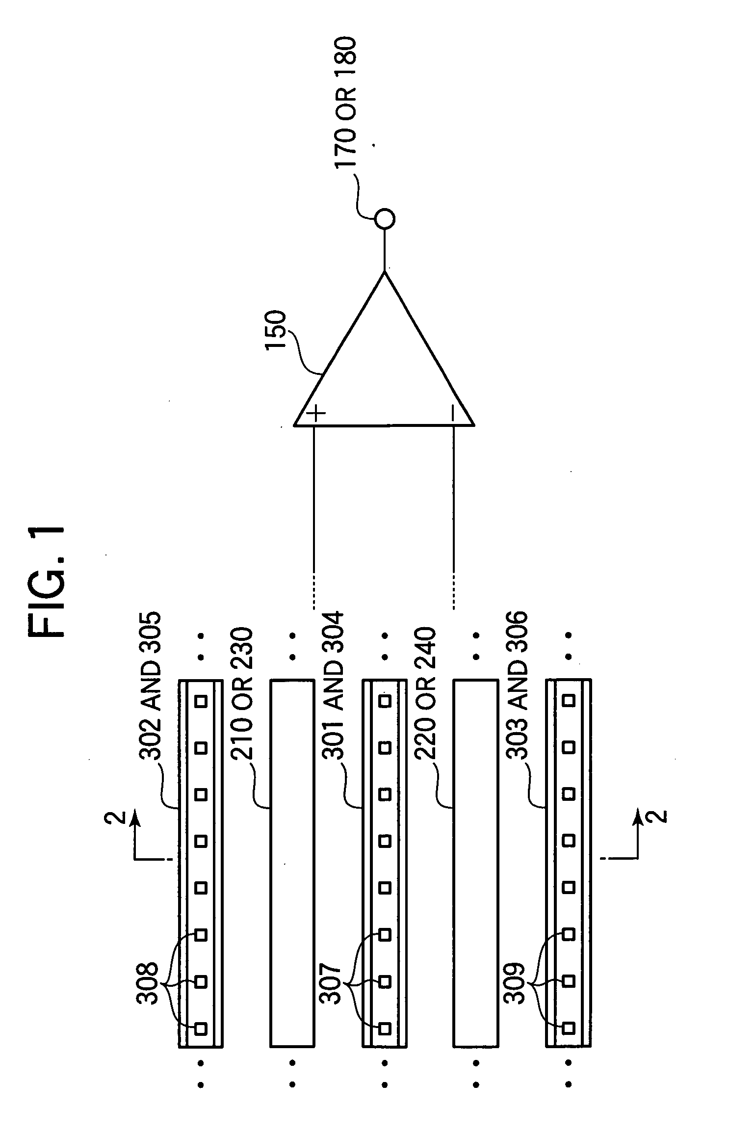
[0028] In the embodiments, shields which are arranged around the first S output line 210 (or the second S output line 230) and the first N output line 220 (or the second N output line 240) differ from those shown in FIGS. 6 and 7.

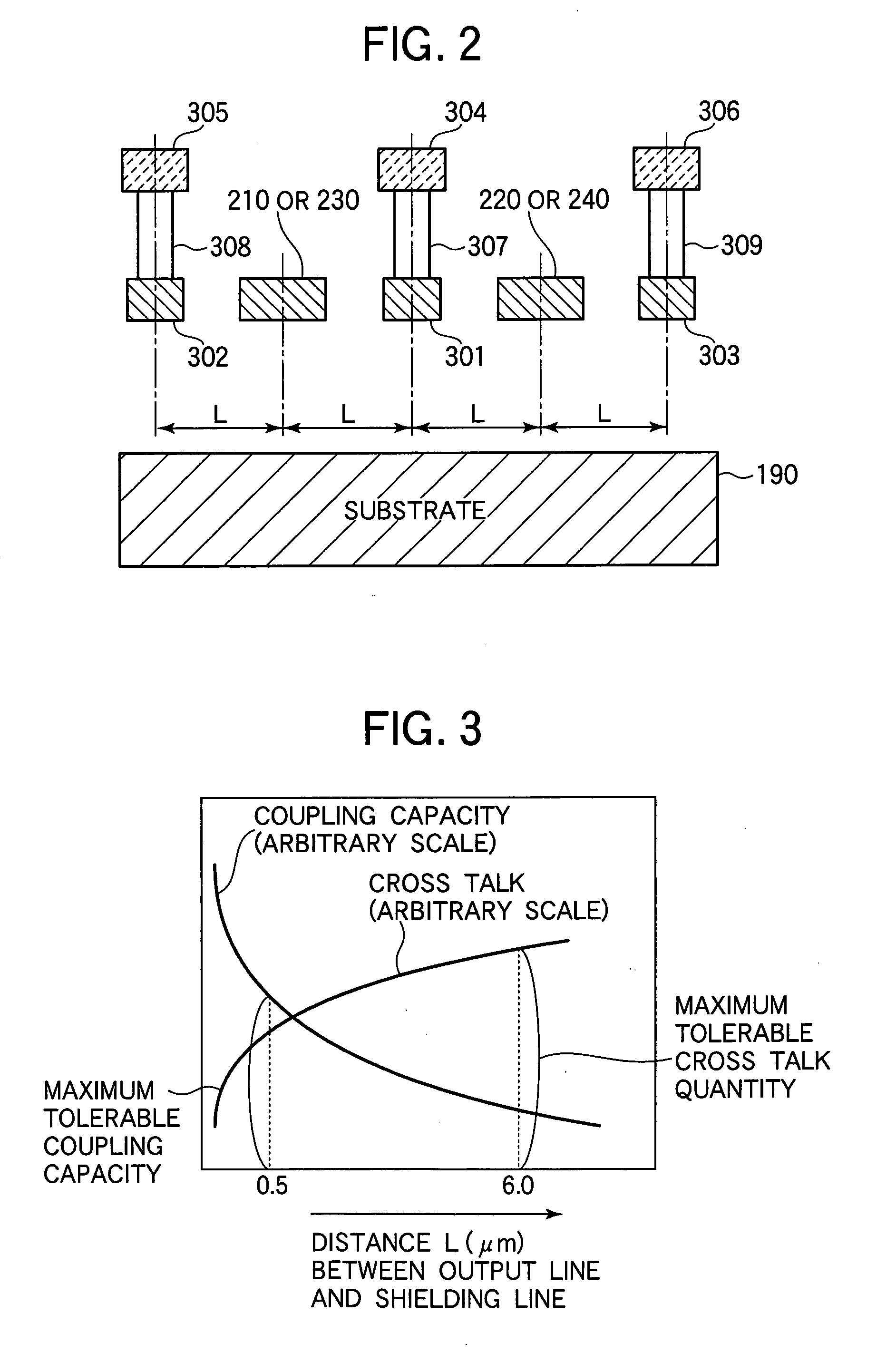
[0029]FIG. 1 is a plan view showing the first S output line 210 (or the second S output line 230), the first N output line 220 (or the second N output line 240), and shields such as shielding lines arranged around those output lines and the like. FIG. 2 is a cross sectional view taken along the line 2-2 in FIG. 1.

[0030] An explanation will be made hereinbelow with respect to the first S output line 210 (the first N output line 220) and since the sec...


PUM


Abstract

A solid state image pick-up device has shields for suppressing deterioration in a ratio of an output signal to output noises caused by crosstalks, suppressing deterioration in a ratio of the output signal to output noises caused by a coupling capacity, and suppressing deterioration in a ratio of the output signal to output noises caused by imbalance is provided. Shielding lines 301, 302, and 303 are arranged in a layer to which output lines 210 and 220 belong. Shielding lines 304, 305, and 306 are arranged over the shielding lines 301, 302, and 303, respectively. Further, shielding pins 307, 308, and 309 are arranged between the shielding lines 301 and 304, between the shielding lines 302 and 305, and between the shielding lines 303 and 306, respectively. No shielding line is arranged over output lines 210 and 220. A structure is made to be plane-symmetrical with respect to a plane including a center line of the shielding line 301 and a plane including a center line of the shielding line 304.

Description

BACKGROUND OF THE INVENTION [0001] 1. Field of the Invention [0002] The invention relates to a solid state image pick-up device for photographing a still image or a motion image and outputting a still image signal or a motion image signal. [0003] 2. Related Background Art [0004] Solid state image pick-up devices are mainly classified into a CCD sensor and a MOS type sensor. Generally, while the CCD sensor is excellent in its small amount of noises, it has such a drawback that electric power consumption is large. On the other hand, despite such an advantage of the MOS type sensor that its electric power consumption is much smaller than that of the CCD sensor, it generally has such a drawback that a noise amount is slightly large. However, there is a tendency toward a decrease in the noise amount in the MOS type sensor and it is expected that the MOS type sensor provides performance equivalent to or better than that of the CCD sensor in the future. [0005] In the MOS type sensor, it is...

Claims


Application Information

Patent Timeline
IPC IPC(8): H04N5/225H01L27/146H04N5/335H04N5/359H04N5/361H04N5/365H04N5/374
CPCH01L27/14603
Inventor OKITA, AKIRAHIYAMA, HIROKITAKADA, HIDEAKI
Owner CANON KK
Learn More