Semiconductor DBR Laser

a semiconductor and dbr technology, applied in semiconductor lasers, laser optical resonator construction, laser details, etc., can solve the problems of reducing the optical performance of the corresponding dbr section, and achieve the effect of reducing the length of the semiconductor chip and reducing back reflections

Active Publication Date: 2015-10-08
LUMENTUM TECH UK LTD
View PDF2 Cites 13 Cited by
  • Summary
  • Abstract
  • Description
  • Claims
  • Application Information

AI Technical Summary

Benefits of technology

[0024]The first DBR section may comprise a curved optical waveguide and the grating may have grating lines that are parallel. Advantageously, such a first DBR section may reduce the length of the semiconductor chip on which the laser is formed, where a curved waveguide is provided adjacent the edge of the chip to reduce back reflections from the facet (e.g. curved to meet the facet at about 7° from the perpendicular, in the case of InP-based semiconductor materials).

Problems solved by technology

Yet, further, such a laser may have a shorter DBR section, without reducing the optical performance of the corresponding DBR section.

Method used


Image

  • Semiconductor DBR Laser
  • Semiconductor DBR Laser
  • Semiconductor DBR Laser

Examples


Embodiment Construction

[0040]In the described embodiments, like features have been identified with like numerals, albeit in some cases having one or more of: increments of integer multiples of 100 and typographical marks (e.g. primes). For example, in different figures, 100, 200, 200′, 300 and 400 have been used to indicate a single longitudinal mode DBR laser.

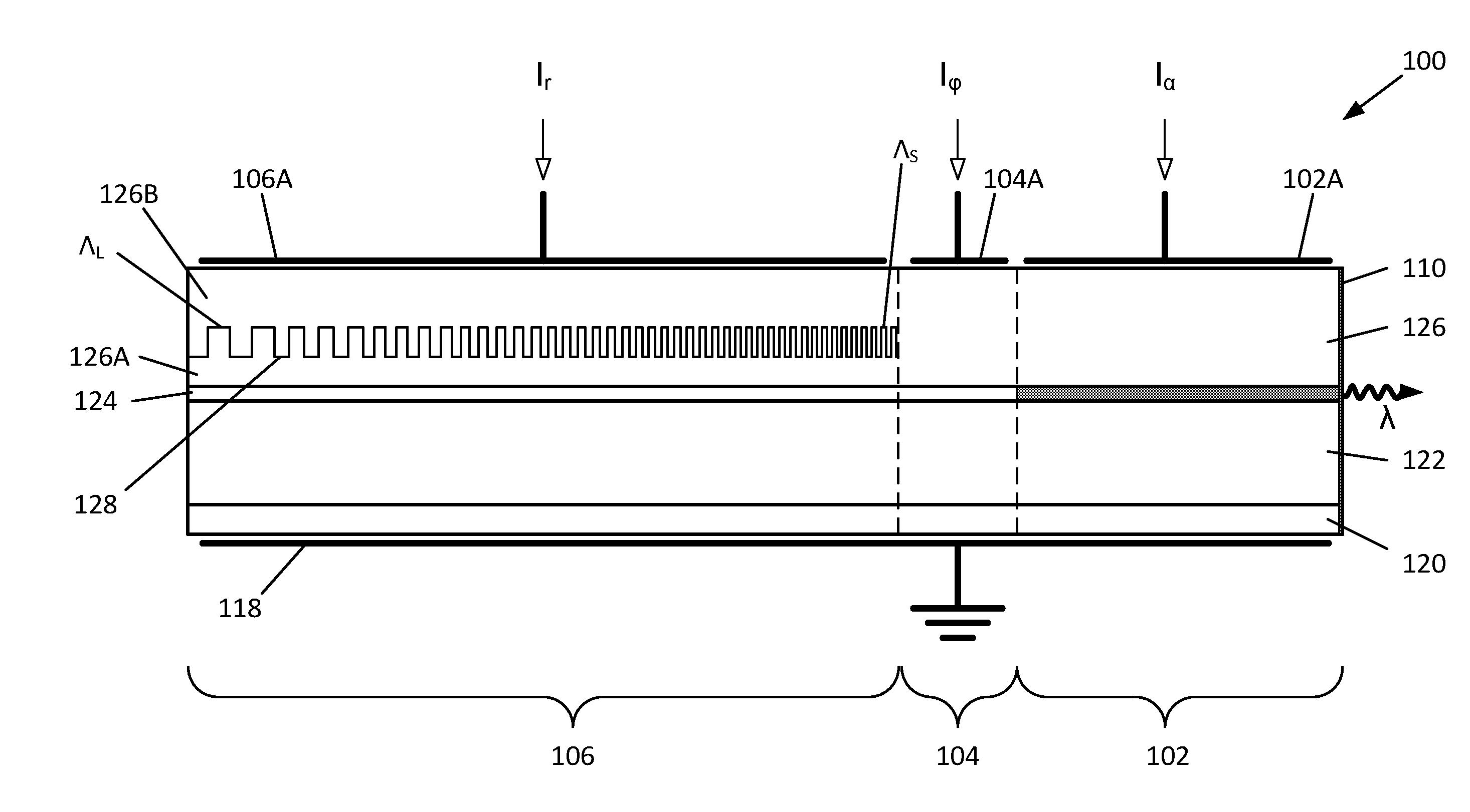
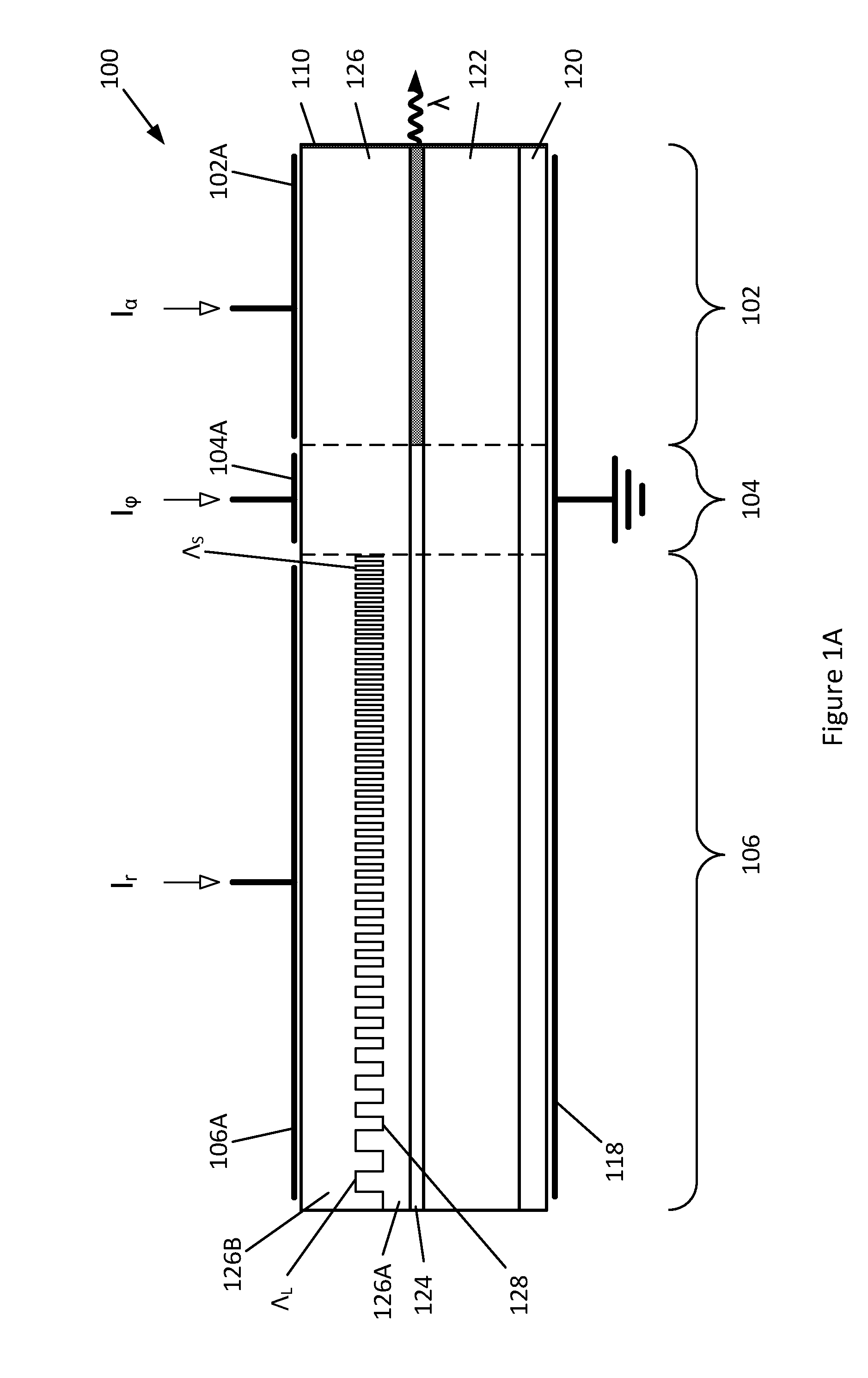
[0041]FIG. 1A illustrates the structure of a three-section single mode distributed Bragg reflector (DBR) laser 100 comprising an optical gain section 102 and a phase control section 104 that are within a laser cavity (in use) formed between a DBR section 106 (first laser cavity end reflector) and a broadband front facet reflector 110 (second laser cavity end reflector). The gain, phase and DBR sections 102, 104 and 106 have respective control electrodes 102A, 104A and 106A arranged to drive control currents Iα, Iφ, Ir through the laser's optical waveguide to a common ground electrode 118.

[0042]The laser 100 is a laser diode structure formed on a sem...


PUM


Abstract

A semiconductor distributed Bragg reflector laser configured for single longitudinal mode operation, having an optical waveguide comprising an optical gain section, a first reflector being a first distributed Bragg reflector (DBR) section comprising a grating configured to produce a reflection spectrum having one or more first reflective peaks, and a second reflector, wherein the first DBR section is configured to compensate for thermal chirp that is induced inhomogeneously along the length of the DBR section, in use.

Description

[0001]The present invention relates to semiconductor distributed Bragg reflector lasers that are configured for lasing operation on a single longitudinal cavity mode, and more particularly, but not exclusively, to widely wavelength tunable distributed Bragg reflector lasers.BACKGROUND[0002]Semiconductor lasers are known that are configured to lase on a single longitudinal mode of the laser cavity, with the lasing mode and its wavelength being selected by a distributed Bragg reflector grating (DBR) having a narrow reflective peak. Such single longitudinal mode lasers have a side mode suppression ratio (SMSR) of at least 25 dB.[0003]DBR lasers configured to operate at a fixed wavelength or to be tunable over a narrow wavelength range typically comprise a laser cavity defined between a broadband reflector (e.g. a broadband facet reflector) and a DBR section, and have within the laser cavity an optical gain section and typically a phase control section. The gain section is electrically ...

Claims


Application Information

Patent Timeline
Patent Type & Authority Applications(United States)
IPC IPC(8): H01S5/0625H01S5/12H01S5/10
CPCH01S5/06256H01S5/1212H01S5/1064H01S5/101H01S5/02407H01S5/0261H01S5/1014H01S5/1243H01S5/1246H01S5/125H01S2301/163
Inventor DAVIES, SAMWARD, ANDREWCARTER, ANDREW
Owner LUMENTUM TECH UK LTD
Why Eureka
Try Eureka