
Bipolar RF-photonic transversal filter with dynamically reconfigurable passbands

a bipolar rf-photonic transversal filter and passband technology, applied in the field of photonic links, can solve the problems of filter architecture, 4 will not allow for the arbitrary routing of a given time-delay, and generate timing errors between “taps” with different polarities, and achieve the effect of enhancing the side lobe suppression ratio (slsr) of the filter passband

Active Publication Date: 2007-09-11
HRL LAB
View PDF8 Cites 10 Cited by
  • Summary
  • Abstract
  • Description
  • Claims
  • Application Information

AI Technical Summary

Benefits of technology

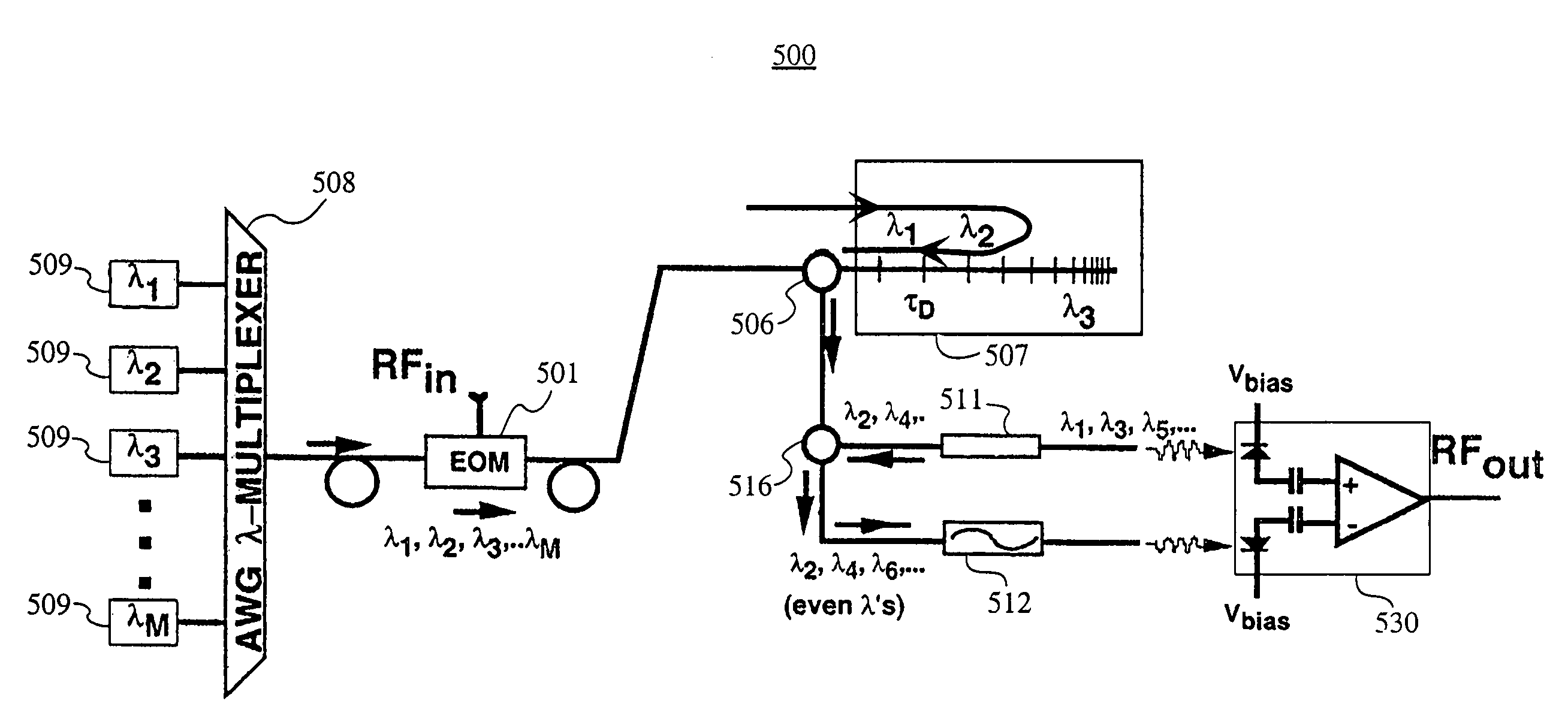
[0022]Disclosed herein is the architecture of a reconfigurable, bipolar RF-transversal filter that may be implemented via the application of wavelength division multiplexed (WDM) and optical-MEMS photonic technologies. Using the disclosed filter architecture, the magnitude as well as polarity (positive or negative) of the filter's tap-coefficients, an, can be selectively set. For example, the filter tap coefficients, an, can be apodized to enhance the side lobe suppression ratio (SLSR) of the filter's passbands. The additional control of the polarity for an allows for the synthesis of a large class of RF bandpass characteristics. In one specific implementation, the tap-weights of the transversal filter are interlaced in a bipolar fashion. These interlaced bipolar taps will (i) eliminate the filter's low-pass response (centered at DC), i.e., the first passband of the filter is offset from DC; and (ii) offer a free spectral range (FSR) that is precisely 2(fc)1, where (fc)1 is the center frequency of the first passband. The DC-offset passbands (e.g. Gaussian or rectangular) of these tap-interlaced bipolar filters are of great interest to the frequency channelization of microwave signals via the use of RF photonics.
[0023]Also disclosed is the architecture of an RF-photonic transversal filter that combines the advantages of (i) agile bandpass synthesis and reconfigurability, with (ii) a disclosed implementation that uses only one dispersive time-delay element—specifically, one chirped fiber grating—to generate the requisite time-delays for the filter. The latter advantage eliminates, in particular, the need to find matching chirped fiber gratings for the positive and negative taps of the transversal filter.

Problems solved by technology

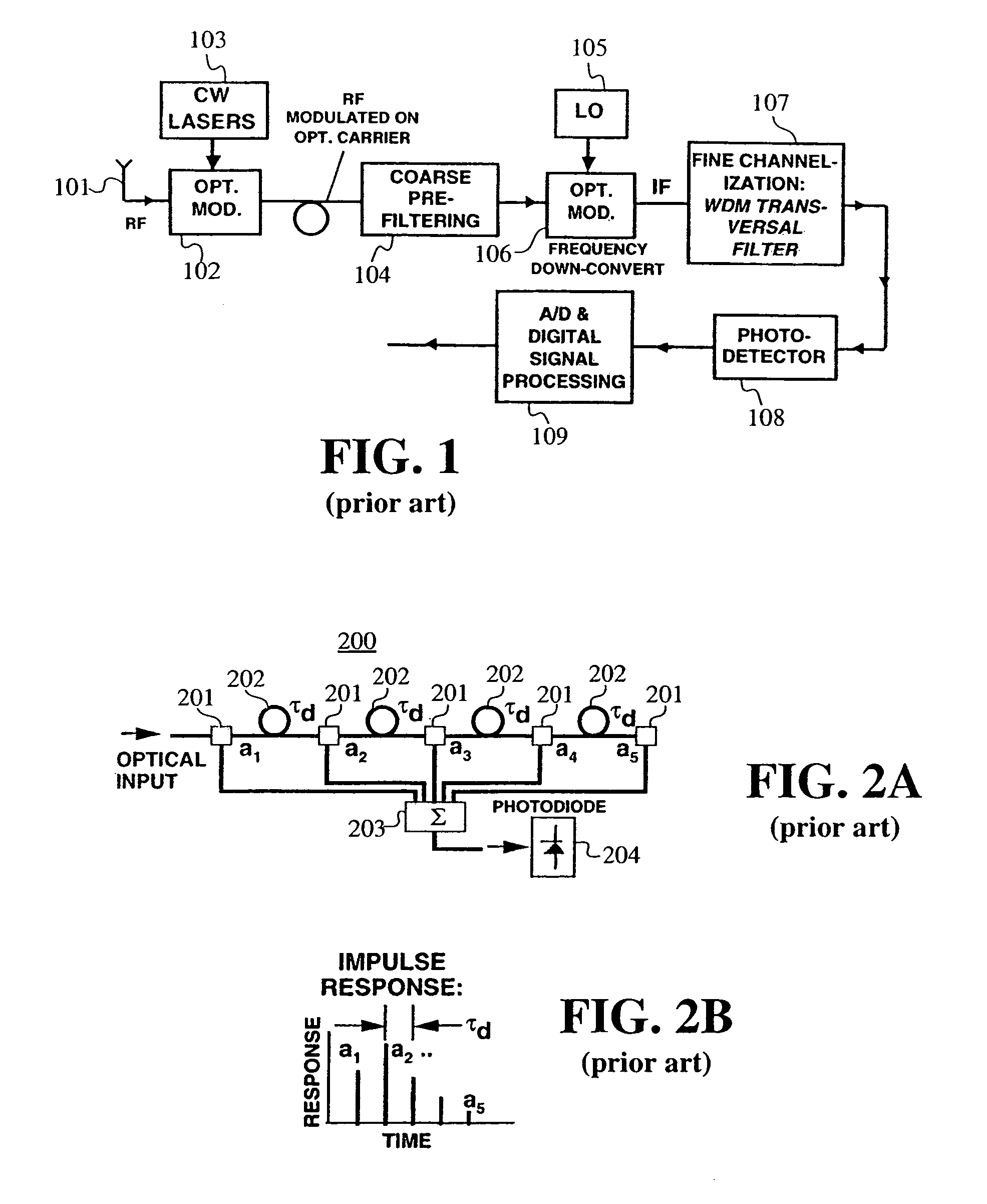
Finally, the single polarity FIR filter depicted in FIG. 2A will always exhibit a low pass response centered at DC—a bandpass feature that is undesirable for frequency channelization applications.
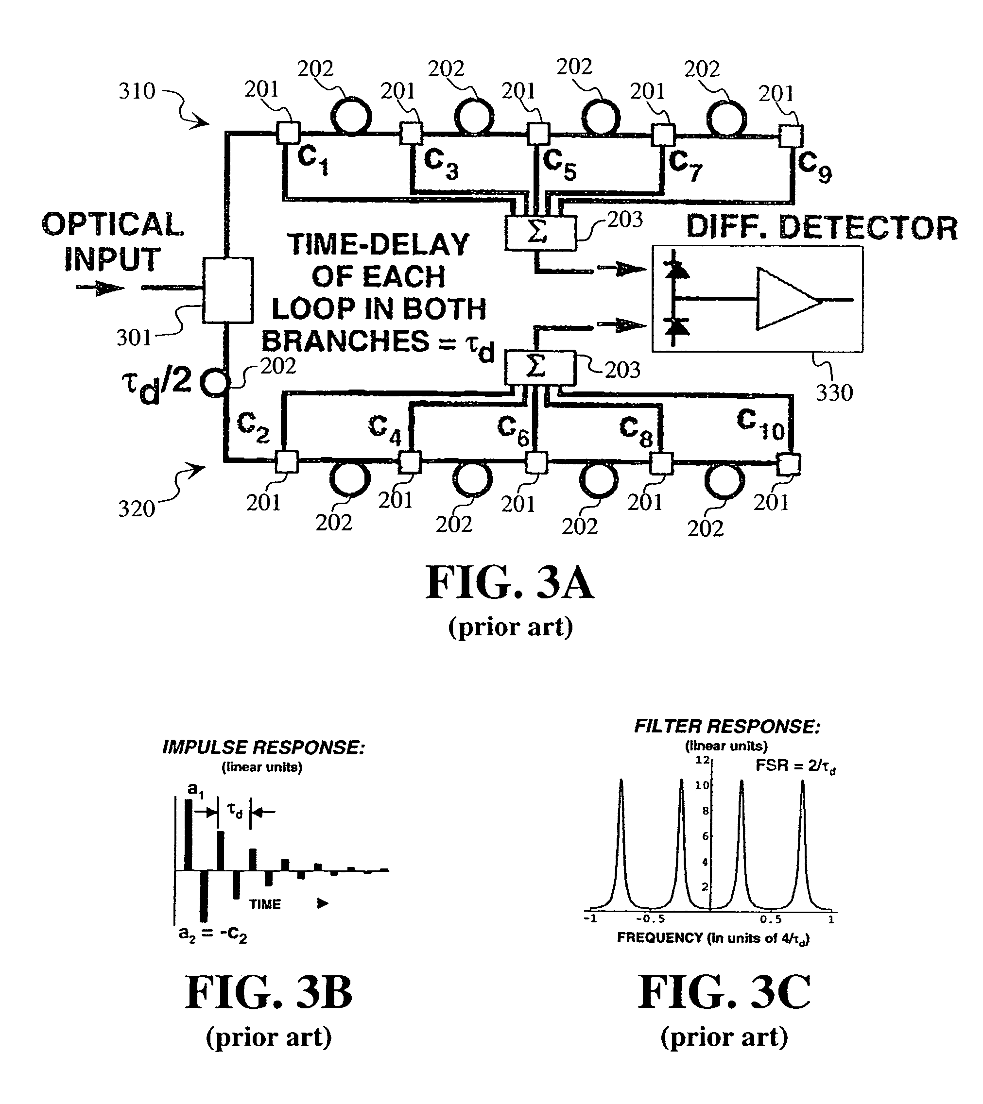
Otherwise, timing errors between “taps” with different polarities will be generated.
Finally, the filter architecture shown in FIG. 4 will not allow for the arbitrary routing of a given time-delay “tap” (e.g. that for the time-delay k1τ0+k2Δt0, where k12

Method used


Image

  • Bipolar RF-photonic transversal filter with dynamically reconfigurable passbands
  • Bipolar RF-photonic transversal filter with dynamically reconfigurable passbands
  • Bipolar RF-photonic transversal filter with dynamically reconfigurable passbands

Examples


Embodiment Construction

[0047]This disclosure describes filter configurations that may be used for the channelization of RF-photonic signals in the frequency domain. A first and second embodiment present architectures that provide FIR transversal filters with apodized, interlaced bipolar tap coefficients (an). In these embodiments, the tap coefficients, an, may be varied via the control of the optical powers emitted by an array of WDM laser sources. A third embodiment presents a filter architecture where tap coefficients can be agilely reconfigured in both polarity and magnitude. In these embodiments, only one chirped fiber-grating is needed to implement a series of wavelength-dependent tap-weights. The filter designs may also be configured to eliminate the low-pass response centered at DC, allowing the placement of the center frequency (fc)1 of the first passband at a targeted intermediate frequency (IF).

[0048]FIG. 5 shows a schematic of a photonic link system 500 in which the first embodiment is used. As...


PUM


Abstract

An architecture that enables one to realize a FIR transversal filter with apodized, interlaced bipolar tap coefficients (an). The tap coefficients, an, are varied via the control of the optical powers emitted by an array of WDM laser sources. Also, a filter architecture where tap coefficients can be agilely reconfigured in both polarity and magnitude. One chirped fiber-grating may be used to implement a series of wavelength-dependent tap-weights. The filter designs can be utilized to eliminate the low-pass response centered at DC, allowing one to place the center frequency (fc)1 of the first passband at a targeted intermediate frequency (IF).

Description

STATEMENT REGARDING FEDERALLY SPONSORED RESEARCH OR DEVELOPMENT[0001]“The invention described herein was made in the performance of work under a DARPA Analog Signal Processing contract, and is subject to the provisions of Public Law F33615-02-C1184 in which the Contractor has elected to retain title.BACKGROUND[0002]1. Field[0003]The present disclosure relates to the use of photonic links for signal distribution in antenna systems. More particularly, the present disclosure relates to a reconfigurable, bipolar RF-transversal filter that may be implemented via the application of wavelength division multiplexed (WDM) and optical-MEMS photonic technologies.[0004]2. Description of Related Art[0005]To discuss the closest prior art, some technical background for the synthesis of finite impulse response (FIR) transversal filters will be provided.[0006]In general, photonic transversal filters may enable one to accomplish an assortment of signal processing operations. These signal processing o...

Claims


Application Information

Patent Timeline
Patent Type & Authority Patents(United States)
IPC IPC(8): G02B6/26G02B6/34H04B10/12
CPCG02B6/12019G02B6/2932G02B6/29395H04B10/25759G02B6/02085
Inventor NG, WILLIEWALSTON, ANDREWHAYES, ROBERT R.
Owner HRL LAB
Learn More