Relay apparatus, communication system and relay method
- Summary
- Abstract
- Description
- Claims
- Application Information
AI Technical Summary
Benefits of technology
Problems solved by technology
Method used
Image

Examples
first embodiment
(A) First Embodiment
[0024] The following is a detailed explanation of a preferred embodiment in which the relay apparatus, the communication system and the relay method according to the present invention are adopted in a wireless access system, given in reference to attached drawings. It is to be noted that in this specification and the attached drawings, the same reference numerals are assigned to components having substantially identical functions and structural features to preclude the necessity for a repeated explanation thereof.
(A-1) Structure Adopted in the Embodiment
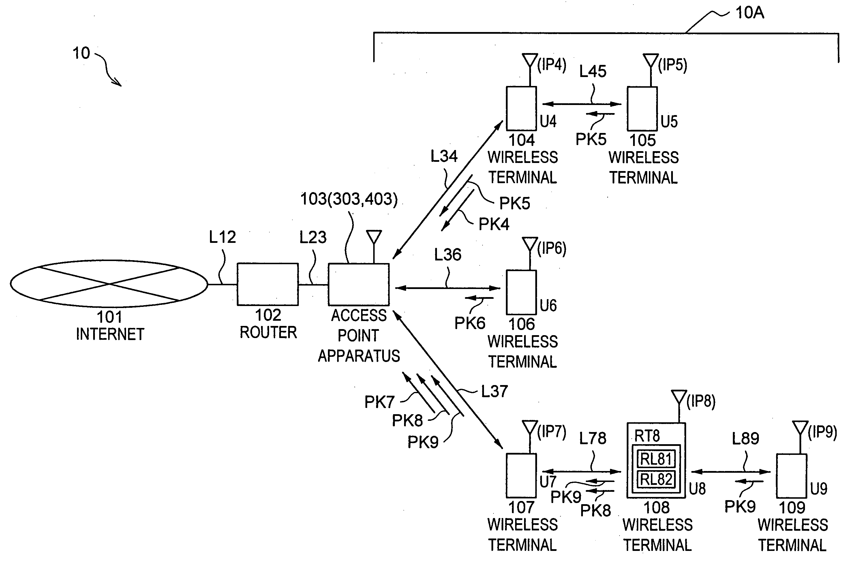
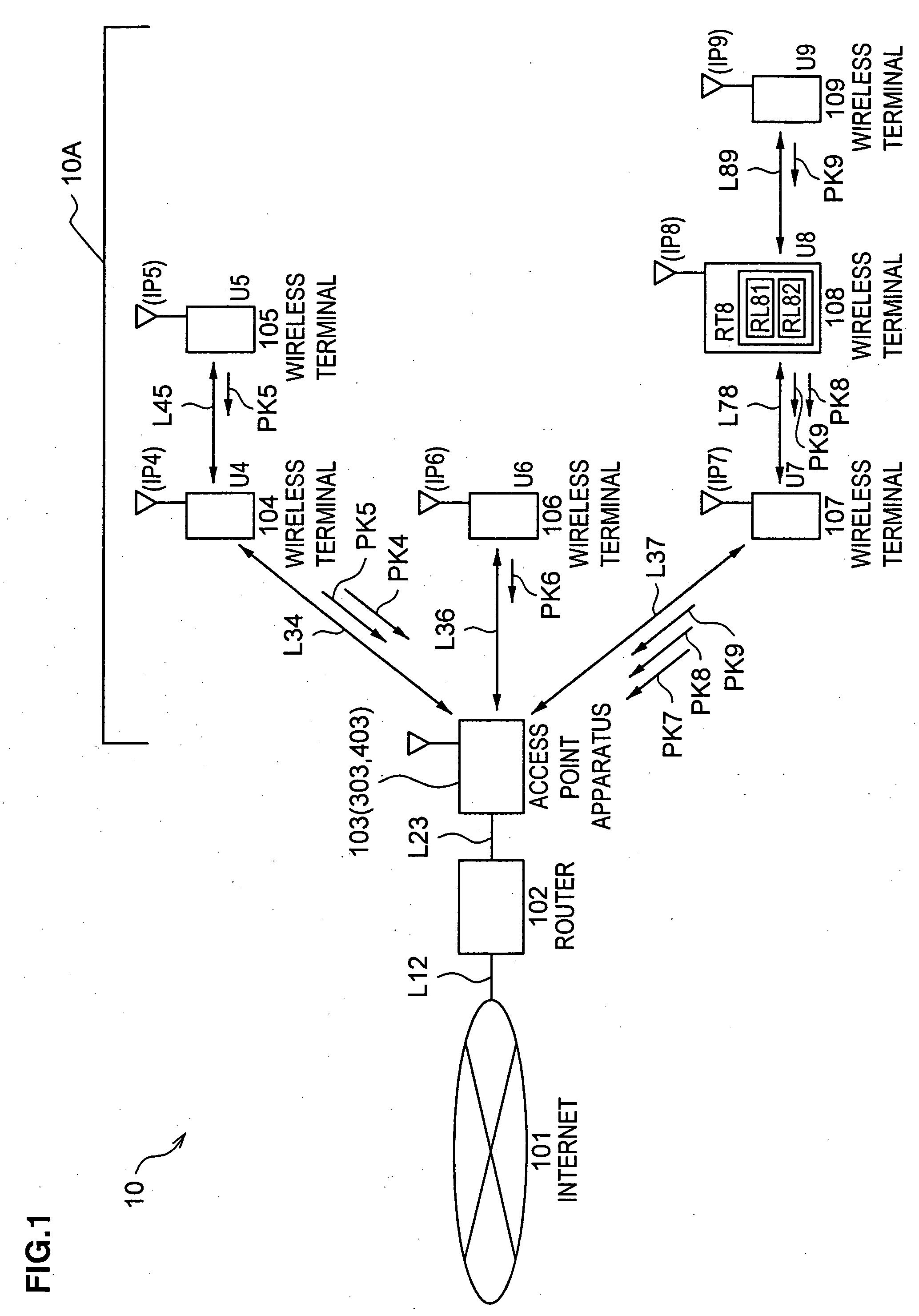
[0025]FIG. 1 shows an example of an overall structure that may be adopted in a wireless access system 10 achieved in the embodiment.
[0026] The wireless access system 10 in FIG. 1 includes the Internet 101, a router 102, an access point apparatus 103, wireless terminals 104 through 109 and transmission paths (links) L12, L23, L34, L36, L37, L45, L78 and L89.
[0027] While another network may substitute for the I...
second embodiment
(B) Second Embodiment
[0094] The following explanation focuses on the features of the second embodiment that differentiate it from the first embodiment.
[0095] The embodiment differs from the first embodiment in that finer control is implemented by taking into consideration the number of packets relayed at each wireless terminal.
(B-1) Structure and Operation of the Second Embodiment
[0096] The structural difference between the second embodiment and the first embodiment is in the internal structure adopted in the access point apparatus.
[0097]FIG. 5 shows an example of the internal structure that may be adopted in an access point apparatus 303 in the embodiment.
[0098] Since the functions of the components assigned with the same names as those of the components in FIG. 2 among components 501 to 508 in FIG. 5 match the functions achieved in the first embodiment, they are not explained in detail here.
[0099] The access point apparatus 303 in the embodiment shown in FIG. 5 only differs...
third embodiment
(C) Third Embodiment
[0114] The following explanation focuses on the features of the third embodiment that differentiate it from the first and second embodiments.
[0115] While the transmission bands allocated to the individual wireless terminals are controlled through the buffering function of the access point apparatus in the first and second embodiments, the transmission bands are controlled in the embodiment by using a flow control function with which most communication terminals used in TCP / IP networks and the like come equipped.
[0116] The embodiment may be considered to be more similar to the second embodiment than the first embodiment in that control is implemented based upon the results of measurement of the numbers of relayed packets.
(C-1) Structure and Operation of the Third Embodiment
[0117] The structural difference between the third embodiment and the second embodiment is in the internal structure adopted in the access point apparatus.
[0118]FIG. 7 shows an example an ...
PUM
 Abstract
Description
Claims
Application Information
 - R&D
- Intellectual Property
- Life Sciences
- Materials
- Tech Scout
- Unparalleled Data Quality
- Higher Quality Content
- 60% Fewer Hallucinations
Browse by: Latest US Patents, China's latest patents, Technical Efficacy Thesaurus, Application Domain, Technology Topic, Popular Technical Reports.
© 2025 PatSnap. All rights reserved.Legal|Privacy policy|Modern Slavery Act Transparency Statement|Sitemap|About US| Contact US: help@patsnap.com