System clock synchronization in an ad hoc and infrastructure wireless networks

a wireless network and system clock technology, applied in the direction of synchronisation arrangement, data switching network, selective content distribution, etc., can solve the problems of inability to meet synchronization requirements, inability to meet clock synchronization requirements, and higher “presentation” delay

Inactive Publication Date: 2005-08-04
SHARP KK
View PDF8 Cites 94 Cited by
  • Summary
  • Abstract
  • Description
  • Claims
  • Application Information

AI Technical Summary

Benefits of technology

[0020] Another object of the invention is to provide a means to synchronize the clocks in different stations in a network without using a conventional master / slave clock paradigm.

Problems solved by technology

In an ad hoc network especially, but also in situations where a Direct Link Protocol is used, as in 802.11e, the clock may not be accurate enough to meet these requirements or may not be able to meet synchronization requirements because of the presence of hidden stations.
Without such synchronization capability, a higher “presentation” delay may be encountered as a result of attempts to synchronize from higher layers alone.
This assumption may not be valid in a typical home network using a PHY layer having a limited range, such as ultra-wide band (UWB), or when Direct Link Protocol (DLP) is used.

Method used


Image

  • System clock synchronization in an ad hoc and infrastructure wireless networks
  • System clock synchronization in an ad hoc and infrastructure wireless networks
  • System clock synchronization in an ad hoc and infrastructure wireless networks

Examples


first embodiment

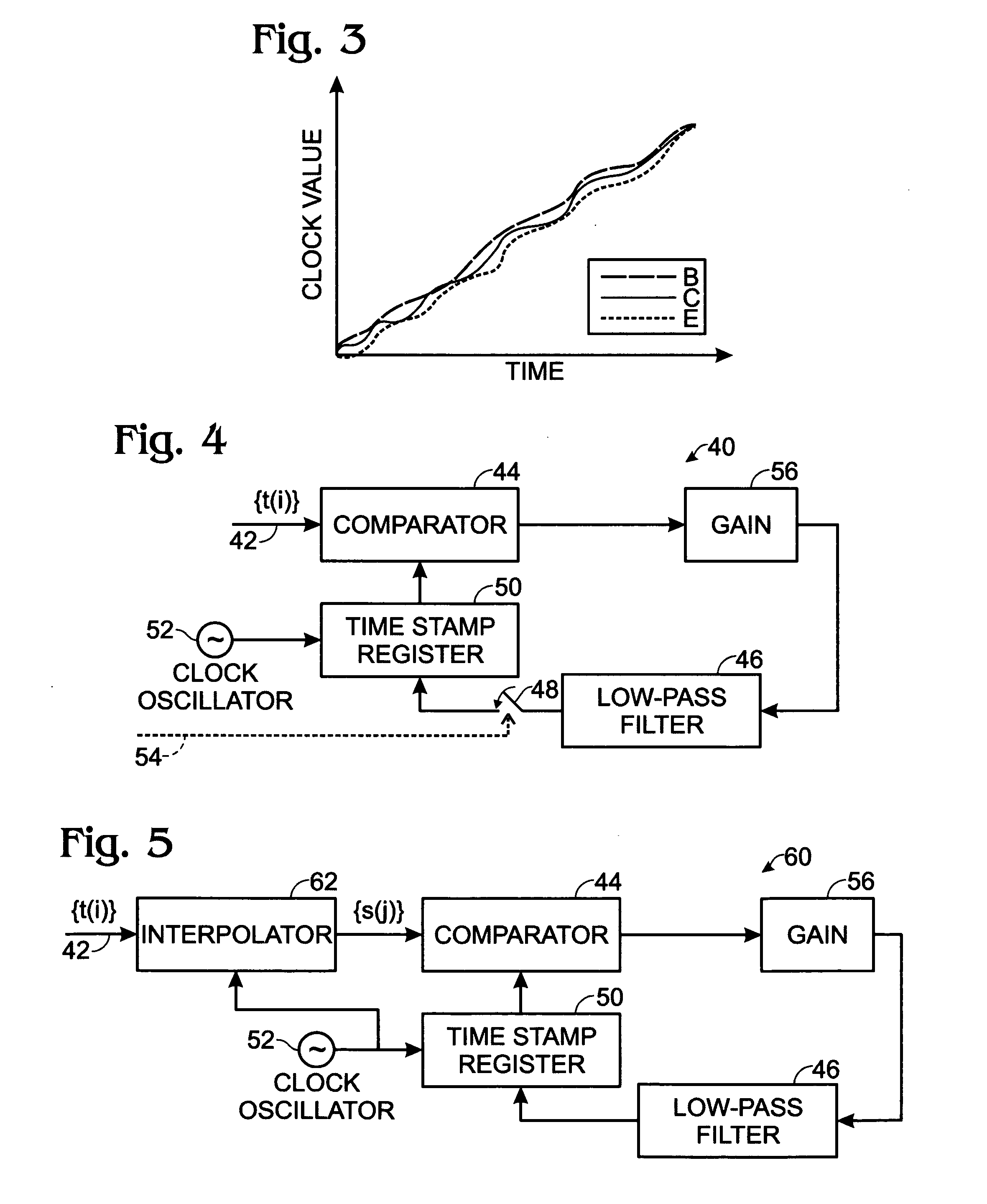
[0032] In the invention, each receiving station replaces the value of its own clock with the received clock value. However, there is a potential problem with this technique if the station has to make a drastic adjustment to its own clock should it receive a frame from a station that has drifted substantially, or has just entered the network and has not fully synchronized itself to the system. This may affect a clock that is already being used to control other transmissions, especially the MPEG-2TS transport. In another embodiment, the received clock value is fed into a Delay Locked Loop (DLL) circuit whose output is fed to a low-pass filter, having a long time-constant, which ultimately adjusts the clock. This ensures that the synchronization is done in a more gradual manner without affecting the transport of the applications.

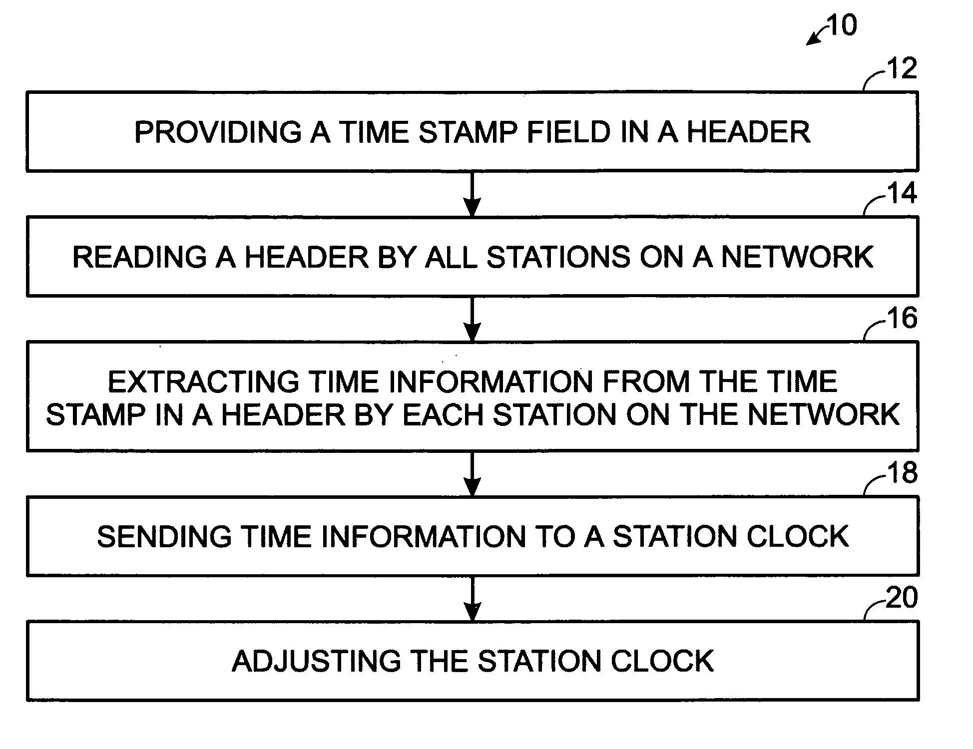
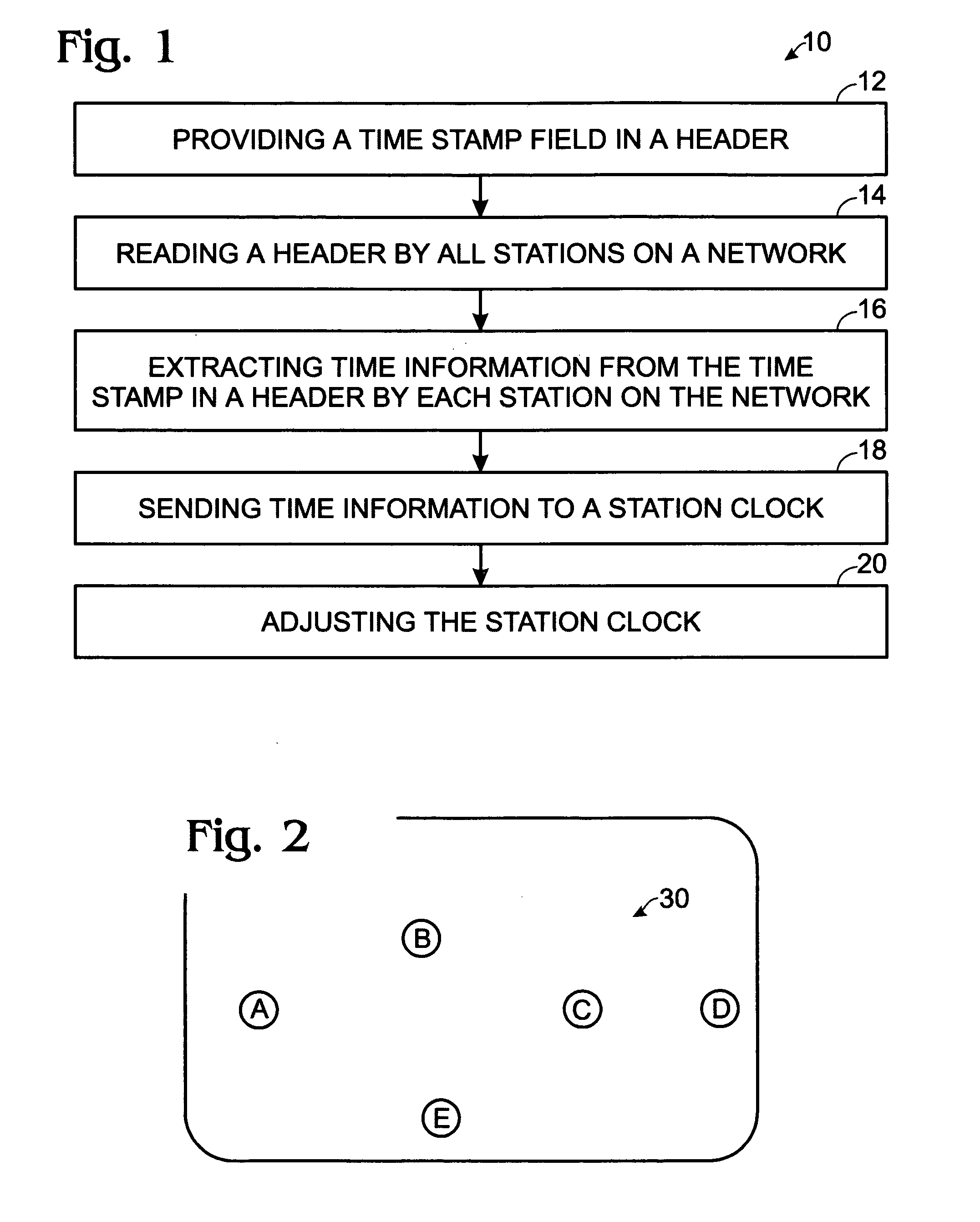
[0033] To ensure that all stations' clocks remain synchronized to the same value, included in the header in all data and management frames is a “Time Stamp” as...

third embodiment

[0046]FIG. 6 shows a full state feedback mechanism based on the clock recovery mechanism.

[0047] The preferred embodiment is a combination of the first embodiment and the remaining embodiments, depicted in FIGS. 4-6, depending on whether the clock is being acquisitioned for the first time or whether the clock is in a tracking mode. ???


PUM


Abstract

A method of synchronizing clocks in the stations of ad hoc and infrastructure networks includes providing a time stamp field in a header; reading the header by all stations in a network; extracting the time stamp information from the header by each station in the network as time information; sending extracted time information to a station clock; and adjusting the station clock as a function of the extracted time information. A system for synchronizing clocks in the stations of ad hoc and infrastructure networks includes a DLL having a comparator for receiving the time stamp information and a low-pass filter having a long time-constant for adjusting the station clock in a gradual manner; a time stamp field in a header; and time information extracted from the time stamp information of the header by each station in the network.

Description

RELATED APPLICATION [0001] This application claims priority from U.S. Provisional Patent Application Ser. No. 60 / 541,707, for System Clock Synchronization in an Ad Hoc and Infrastructure Wireless Networks, filed Feb. 3, 2004.FIELD OF THE INVENTION [0002] This invention relates to clock synchronization for ad hoc wireless networks, and specifically to a modified PHY header including a time stamp field therein. BACKGROUND OF THE INVENTION [0003] High quality AV requires tight synchronization for MPEG-2TS, and for high quality audio broadcast in stereo, to different locations. These delay requirements are typically of the order of tens of nanoseconds. [0004] In an ad hoc network especially, but also in situations where a Direct Link Protocol is used, as in 802.11e, the clock may not be accurate enough to meet these requirements or may not be able to meet synchronization requirements because of the presence of hidden stations. Without such synchronization capability, a higher “presentat...

Claims


Application Information

Patent Timeline
Patent Type & Authority Applications(United States)
IPC IPC(8): H04B1/69H04J3/06H04L12/28H04L12/56H04W56/00H04W84/18
CPCH04B1/7183H04J3/0664H04W84/18H04N21/4305H04W56/001H04J3/067H04J3/0676
Inventor KANDALA, SRINIVASKOWALSKI, JOHN MICHAELBENNETT, RICHARD THOMAS
Owner SHARP KK
Why Eureka
Try Eureka