Method for monitoring quality of a transmissive laser weld

a technology of transmissive laser and weld, which is applied in the direction of optical radiation measurement, manufacturing tools, instruments, etc., can solve the problems of gas voids in the weld pool, many problems can occur, and the width of the weld pool at that portion may be too narrow

Inactive Publication Date: 2005-08-04
TRW AUTOMOTIVE US LLC
View PDF73 Cites 60 Cited by
  • Summary
  • Abstract
  • Description
  • Claims
  • Application Information

AI Technical Summary

Benefits of technology

[0007] The present invention relates to a method for monitoring quality of a weld being formed between first and second pieces of material. The method comprises the steps of: obtaining a thermal image of the weld being formed by collecting infrared radiation passing through the second piece of material; and analyzing the obtained thermal image for characteristics indicative of a properly formed weld.
[0008] According to another aspect, the present invention relates to a method for monitoring quality of a weld being formed between first and second pieces of material. The method comprises the

Problems solved by technology

Many problems can occur during the formation of a transmissive laser weld.
For example, when a portion of the weld pool is not heated to a proper temperature, i.e., the temperature of the portion is too low, the width of the weld pool at that portion may be too narrow and a weak point or even a void in the weld may result.
On the other hand, when a portion of the weld pool is overheated, i.e., the temperature of the portion is too high, gas voids may form in the we

Method used


Image

  • Method for monitoring quality of a transmissive laser weld
  • Method for monitoring quality of a transmissive laser weld
  • Method for monitoring quality of a transmissive laser weld

Examples


Embodiment Construction

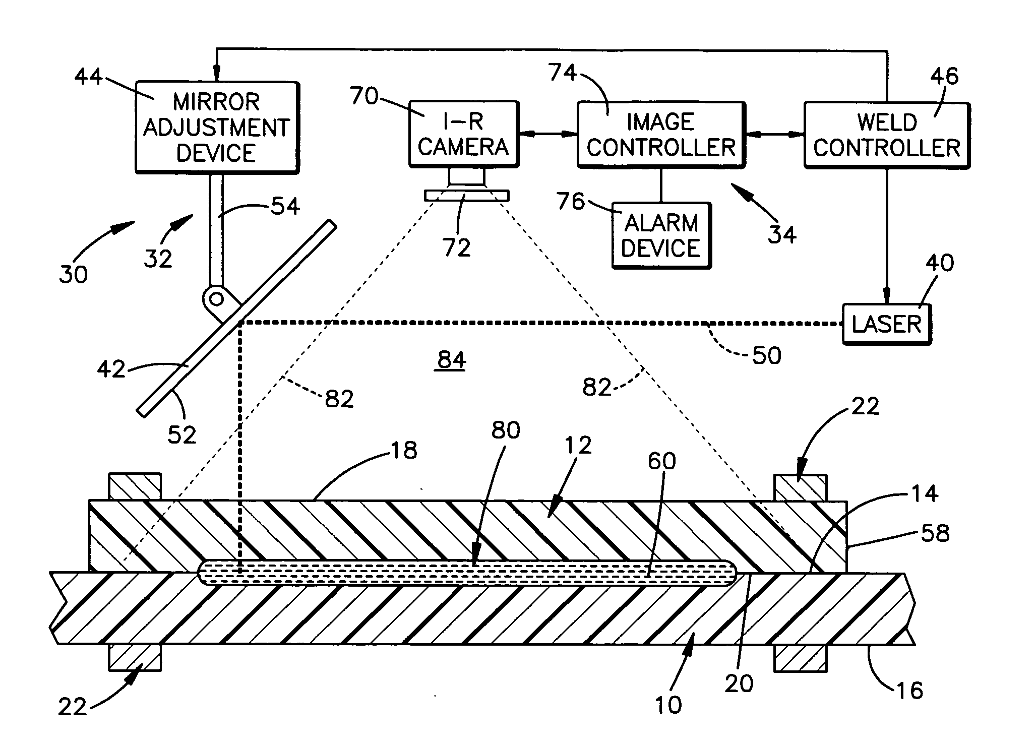
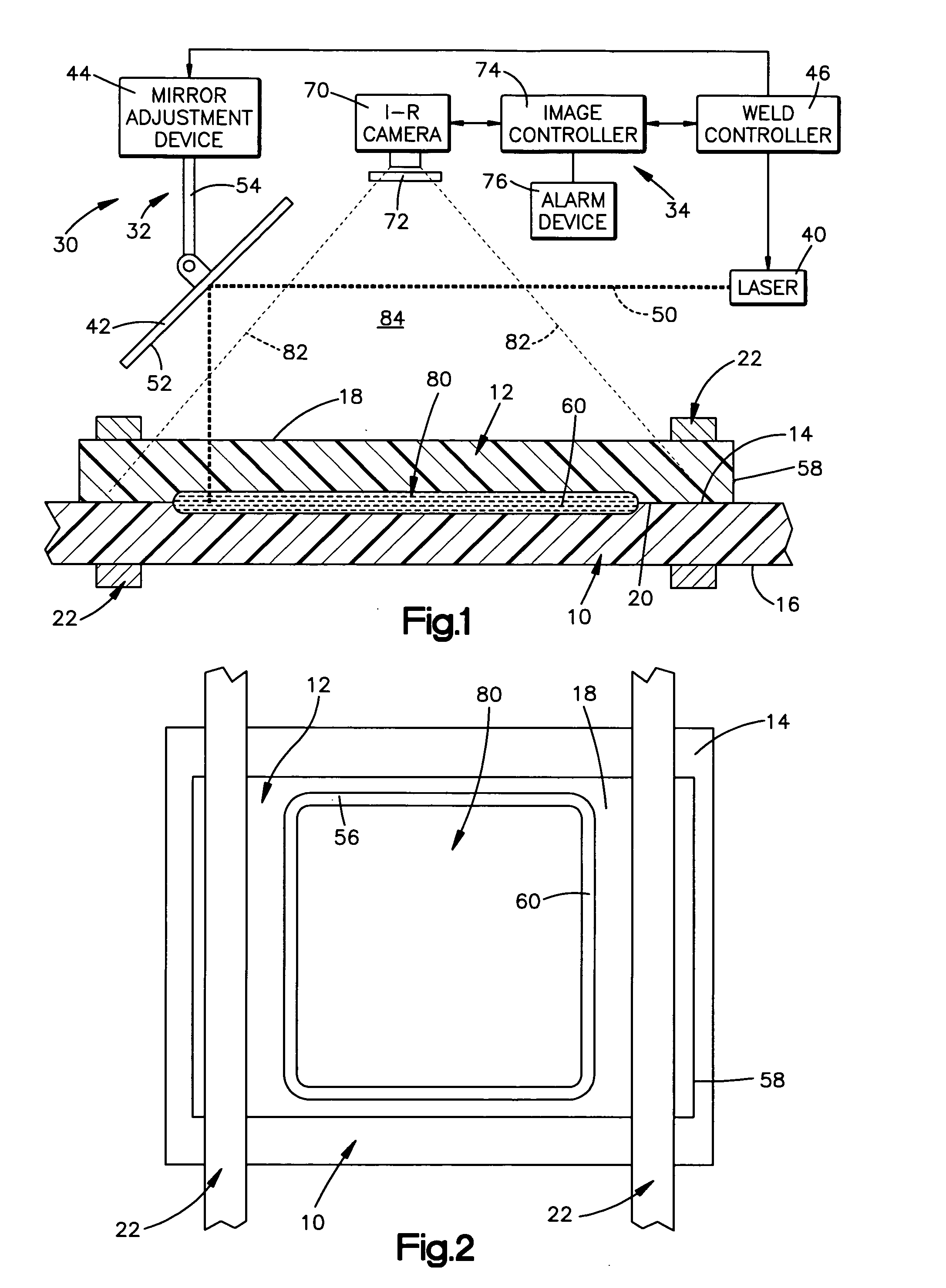
[0013]FIG. 1 schematically illustrates first and second pieces of plastic material 10 and 12, respectively. The first piece of plastic material 10 is generally planar and includes upper and lower surfaces 14 and 16, respectively. Similarly, the second piece of plastic material 12 is generally planar and includes upper and lower surfaces 18 and 20, respectively. FIG. 1 illustrates the second piece of plastic material 12 overlaying the first piece of plastic material 10. Two clamping devices 22 are illustrated in FIG. 1 holding the first and second pieces of plastic material together. When the first and second pieces of plastic material 10 and 12 are held together, the upper surface 14 of the first piece of plastic material 10 abuts the lower surface 20 of the second piece of plastic material.

[0014] The first and second pieces of plastic material 10 and 12 have different material properties. Particularly, the second piece of plastic material 12 is transmissive to a range of infrared ...


PUM

PropertyMeasurementUnit
Temperatureaaaaaaaaaa
Widthaaaaaaaaaa
Wavelengthaaaaaaaaaa

Abstract

A method for monitoring quality of a weld (56) being formed between first and second pieces of material (10 and 12) includes the steps of obtaining a thermal image of the weld (56) being formed by collecting infrared radiation passing through the second piece of material (12); and analyzing the obtained thermal image for characteristics indicative of a properly formed weld (56).

Description

TECHNICAL FIELD [0001] The present invention relates to a method for monitoring the quality of a weld being formed between two pieces of material. More particularly, the present invention relates to a method for monitoring the quality of a transmissive laser weld being formed between two pieces of plastic material. BACKGROUND OF THE INVENTION [0002] Transmissive laser welding is used for bonding together first and second pieces of plastic material. The weld in transmissive laser welding is formed using a beam of electromagnetic energy that is emitted from a laser. One of the two pieces of plastic material, for example, the first piece of plastic material, is transmissive to the beam of electromagnetic energy, i.e., the beam passes through the first piece of plastic material. The other of the two pieces of plastic material, for example, the second piece of plastic material, absorbs the electromagnetic energy of the beam. [0003] During the transmissive laser welding process, the beam ...

Claims


Application Information

Patent Timeline
IPC IPC(8): B23K26/03G01N25/00G01N25/72
CPCB23K26/032G01N25/72B29C65/1635B23K26/034B29C65/1661B29C66/1122B29C66/472B29C66/91216B29C66/91221B29C65/7841B29C66/24245B29C66/53461B29C66/73921B29C65/1654B29C66/961B29C66/9441B29C66/342B29C66/8748
Inventor MURRAY, NEIL G. JR.BENEFIEL, DOUGLAS W.
Owner TRW AUTOMOTIVE US LLC
Why Eureka
Try Eureka