Efficient low-power mode for multicarrier communications

a multi-carrier, low-power technology, applied in the field of digital communications, can solve the problems of high peak-to-average ratio (par) of signal amplitude, inability to load bits in subchannels, and constraints on transmission circuitry, and achieve the effect of substantially reducing the amplitude of output signals

Active Publication Date: 2005-08-04
TEXAS INSTR INC
View PDF5 Cites 24 Cited by
  • Summary
  • Abstract
  • Description
  • Claims
  • Application Information

AI Technical Summary

Benefits of technology

[0018] It is therefore an object of this invention to provide a multi-carrier transmitter and method having a

Problems solved by technology

Indeed, some subchannels may not be loaded with any bits, because of the noise and attenuation in those channels.
However, multicarrier methods such as IDFT modulation can result in a high peak-to-average ratio (PAR) of the signal amplitudes.
The high PAR for conventional DMT signals presents significant constraints on the transmission circuitry, and can greatly complicate the analog circuitry required for high fidelity transmission.
For example, a high PAR requires a large dynamic range at the inputs of digital-to-analog and analog-to-digital converters, necessitating a large number of bits of resolution, thus greatly increasing the cost and complexity of these functions.
Filters and amplifiers must also become more complex and costly in order to handle both the high peak amplitudes and also the resolution required for the vast majority of the samples having lower amplitude.
In addition, the high PAR results in much higher power consumption in the communications circuits, further increasing the cost of the circuits and systems used for DMT transmission and receipt, particularly those circuits often referred to as the analog front end (AFE).
However, once the first link exits its

Method used


Image

  • Efficient low-power mode for multicarrier communications
  • Efficient low-power mode for multicarrier communications
  • Efficient low-power mode for multicarrier communications

Examples


Embodiment Construction

[0036] The present invention will be described in connection with its preferred embodiment, namely as implemented into transceivers for digital subscriber line (DSL) communications. However, it is contemplated that this invention may also be used in other communications contexts, especially those using multicarrier modulation (MCM) techniques. A specific example of another such context is orthogonal frequency division multiplexing (OFDM), as is now being deployed in wireless telephone and wireless network communications. It is contemplated that other communications technologies that may benefit from this invention will be apparent to those skilled in the art having reference to this specification. Accordingly, it is to be understood that the following description is provided by way of example only, and is not intended to limit the true scope of this invention as claimed.

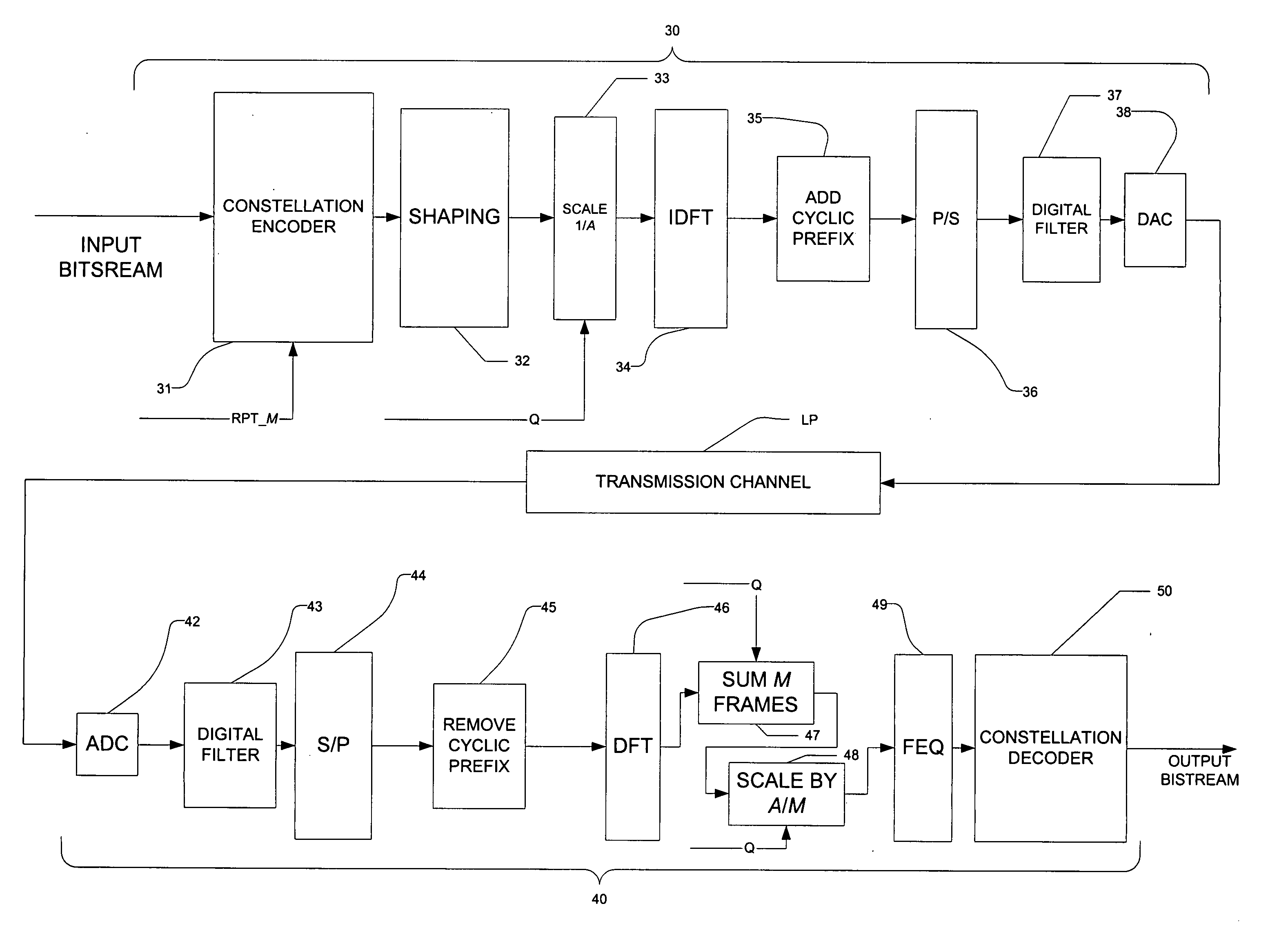
[0037] Referring now to FIG. 3, the data flow of DMT communications according to a first preferred embodiment of ...


PUM


Abstract

Multicarrier modulated communications, involving a transmitting modem (30; 30′) and a receiving modem (40; 40′) that operate according to normal operating mode and a low-power, quiescent, mode, are disclosed. In the quiescent mode, transmitter power is saved by scaling down the amplitude of the transmitted symbols in each frame by a scaling factor (A), and transmitting multiple instances of the frames in sequence. On receipt, the repeated frames are summed, and the summed amplitudes scaled to account for the repetition factor (M) and the scaling factor (A), to recover the transmitted information. If the repetition factor (M) is greater than or equal to the square of the scaling factor (A), the signal-to-noise ratio in quiescent mode is at least as high as that in normal operation. The repeating, scaling, and summing may all be performed in the frequency domain or in the time domain, as desired.

Description

CROSS-REFERENCE TO RELATED APPLICATIONS [0001] This application claims priority, under 35 U.S.C. §119(e), of Provisional Application No. 60 / 541,331, filed Feb. 3, 2004.STATEMENT REGARDING FEDERALLY SPONSORED RESEARCH OR DEVELOPMENT [0002] Not applicable. BACKGROUND OF THE INVENTION [0003] This invention is in the field of digital communications, and is more specifically directed to power reduction techniques in communications involving multiple frequency bands. [0004] An important and now popular modulation standard for digital subscriber line (DSL) communications is Discrete Multitone (DMT). According to DMT technology, the available spectrum is subdivided into many subchannels (e.g., 256 subchannels of 4.3125 kHz). Each subchannel is centered about a carrier frequency that is phase and amplitude modulated, typically by Quadrature Amplitude Modulation (QAM), in which each symbol value is represented by a point in the complex plane; the number of available symbol values depends, of ...

Claims


Application Information

Patent Timeline
IPC IPC(8): H04K1/10H04L1/08H04L27/26
CPCH04L27/2602H04L1/08
Inventor REDFERN, ARTHUR J.
Owner TEXAS INSTR INC
Why Eureka
Try Eureka