Portable vaporizer

a vaporizer and portable technology, applied in the field of portable vaporizers, can solve the problems of not completely serving this purpose, cumbersome devices, and cumbersome devices utilizing flames as heat sources, and achieve the effects of convenient replacement, convenient and efficient operation, and convenient us

Inactive Publication Date: 2005-08-04
ROSENTHAL JOSHUA
View PDF24 Cites 15 Cited by
  • Summary
  • Abstract
  • Description
  • Claims
  • Application Information

AI Technical Summary

Benefits of technology

[0089] A material fastener, beyond human hands, to hold the two vessels in assembled position, is not a necessary part of the invention as the device will function so long as the vessels are in proper relation to one another. However, a fastener to hold the two vessels in proper assembled position does make the device much more convenient and efficient to operate. There are certainly many possible fasteners, including simple fasteners such as a strap or elastic band, which could function successfully as the fastener for the present invention. For most embodiments it is preferable that in assembled position, all parts of the fastener be located away from the heating area so as to avoid heating the fastener and / or interfering with the heating of the heating area. A grommet, made preferably of rubber or other elastic material, has been chosen as a non-limiting example of a fastener here for a number of reasons, including that it is effective, easy to use, inexpensive, unobtrusive, and easily replaceable should it wear out.
[0090] A number of materials can be successfully employed for construction of the vessels of the present invention, including glass, metal, and ceramic, as well as combinations of material such as metal bonded to glass, etc. High temperature glass, such as PYREX®, has the advantages of being durable, inexpensive, and transparent. This type of material is also appropriately but not excessively conductive of heat for the current purpose as heat applied to the heating area remains substantially confined to the distal end of the device when the device is made of this material, making the device easier and safer to handle during and after usage. An optional insulating wrap is provided for further protection from heat.

Problems solved by technology

Some devices, however, such as those disclosed in U.S. Pat. Nos. 4,219,032; or 4,340,072, actually make direct use of the hot combustion gases from the fuel source for heating the vaporizable substance and therefore arguably do not completely serve this purpose.
Although they may effectively vaporize vaporizable substances, many of the devices referred to above also have disadvantages:
With the possible exception of the device disclosed in U.S. Pat. No. 1,405,802, those devices mentioned above which utilize a flame as a heat source are certainly too cumbersome to easily be carried in a pocket or purse.
Those devices mentioned above which use electrically generated heated air as the heat source all require a device, either internal or external, to produce such heated air and are made more cumbersome by the inclusion of said electrical air-heating device.
2) release combustion products into the ambient atmosphere which may be offensive and / or hazardous to others in the vicinity as well as to the user of the device.
In addition these devices pose fire hazards similar to burning cigarettes when not properly attended.
1) Many of the devices mentioned in all categories are expensive to produce.
2) Some of the devices hold the vaporizable substance in compartments which are hidden from view, making visual inspection and assessment of the state of the vaporizable substance more difficult once the vaporization process has begun.
In examining the various devices available, it is evident that they suffer from drawbacks similar to those outlined above.
Many of these devices are quite expensive and cumbersome while the less expensive, more portable models are not completely effective at isolating combustion byproducts from desired volatile substances.
In addition, some of the existing models of vaporizer require that the vaporizer, once ‘loaded’ with vaporizable substance, be required to be held relatively still in order to prevent the vaporizable substance from moving out of proper vaporizing position, and are thus unsuitable for transport once ‘loaded’ or for use in relatively unstable physical environments (e.g. during a bumpy car-ride).

Method used


Image

  • Portable vaporizer
  • Portable vaporizer
  • Portable vaporizer

Examples


Embodiment Construction

A) General Description

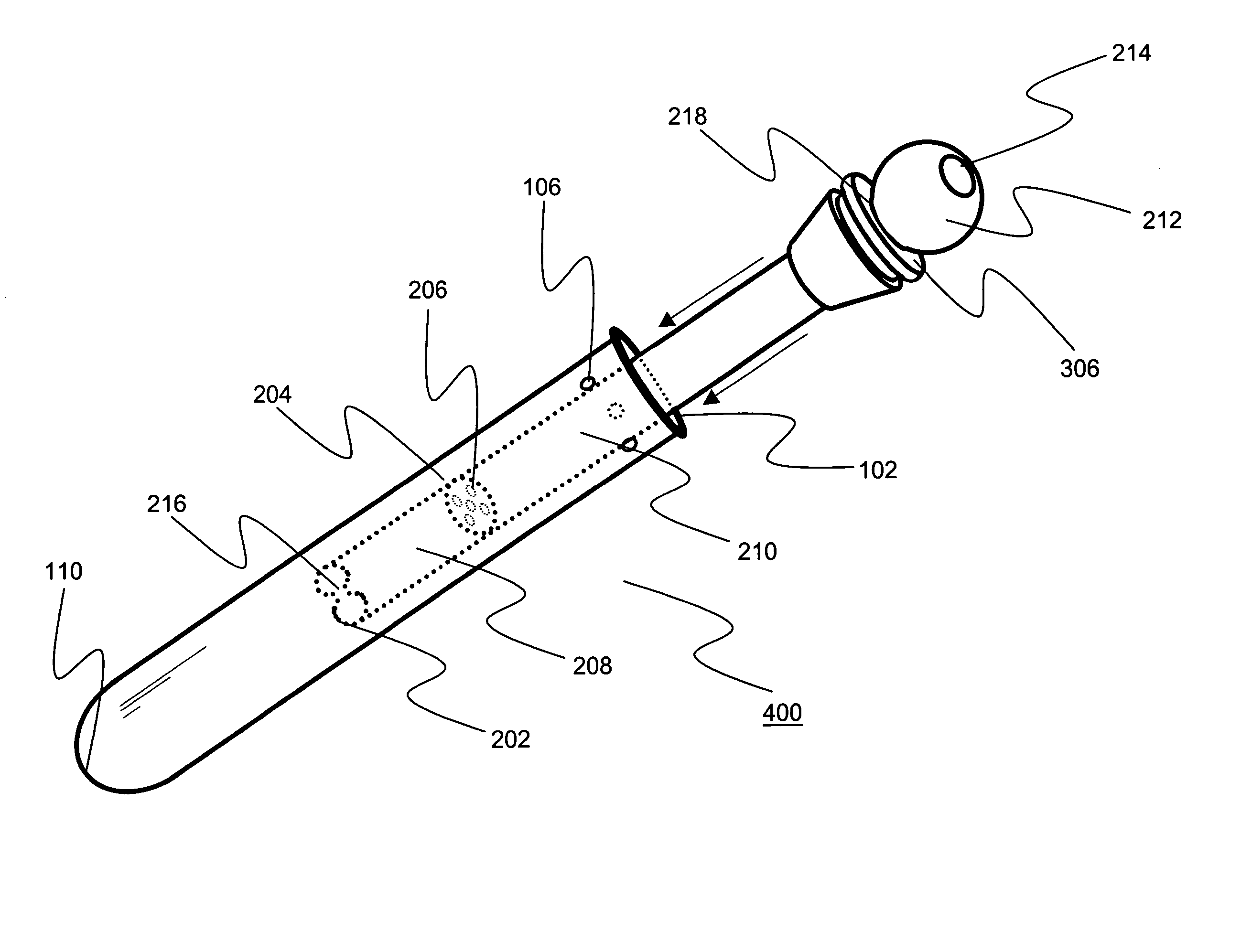
[0092] In one aspect, the present invention teaches a portable vaporizing device, the device generally comprising an outer vessel and an inner vessel held together by a fastener. The invention also optionally comprises an outer insulating wrap.

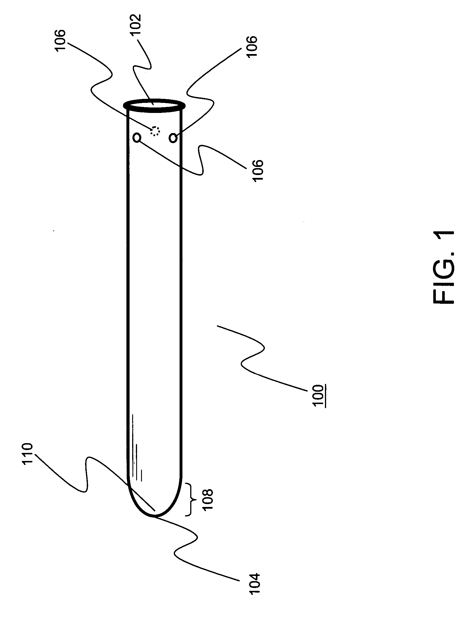
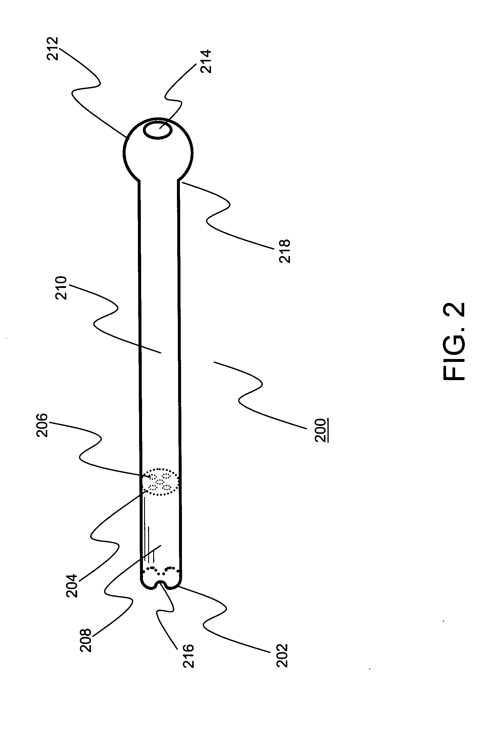
[0093] The outer vessel has a closed distal end and an open proximal end. The inner vessel has an open proximal end as well as an open distal end. The inner vessel also has a partition within it, spanning the inner cross-sectional area of the vessel. The partition divides the inner volume of the inner vessel into two chambers, a vaporization chamber distally and a drawing chamber proximally. The partition also has screening holes through it to allow air to be drawn from the vaporization chamber through the partition into the drawing chamber, while keeping the vaporizable substance in place inside the vaporization chamber, the partition thus functioning essentially as a screening mechanism.

[0094] When the device is assem...


PUM

PropertyMeasurementUnit
thicknessaaaaaaaaaa
inner diameteraaaaaaaaaa

Abstract

The present invention teaches a portable vaporizing device which, through the application of heat, successfully volatilizes one or more constituents of various vaporizable substances, such as medicines and plant materials, for the purpose of inhaling these volatilized constituents. The invention may be successfully operated using the flame from a standard butane cigarette lighter or the like as the sole heat source. An additional embodiment of the device provides a substitute for a standard slider-bowl allowing for the conversion of a standard waterpipe into a vaporizing device. A second additional embodiment allows for vaporization of cigarettes or portions thereof.

Description

BACKGROUND OF THE INVENTION [0001] (1) Field of Invention [0002] This invention relates to the field of heat vaporization of various substances, such as plant substances, medicines, etc., to produce smoke-free inhalable vapors. [0003] (2) Description of Prior Art [0004] Vaporization of volatile constituents of various substances without combustion by the application of heat for the purpose of inhaling said volatile constituents is a process that has been known for quite some time. U.S. Pat. No. 87,603 of Mar. 9, 1869 discloses the construction of a vaporizer which makes use of heated stones, heated metal or coals in an isolated chamber and the conduction of heat therefrom to release volatile constituents from medicinal substances in an adjacent chamber in order to make possible inhalation of said volatile constituents. [0005] Since that time, numerous vaporizing devices of varied design and various levels of sophistication have been disclosed. Some use heat from electrical heating e...

Claims


Application Information

Patent Timeline
Patent Type & Authority Applications(United States)
IPC IPC(8): B32B5/02
CPCA61M11/041A61M11/048A61M15/08A61M15/06A61M11/042
Inventor ROSENTHAL, JOSHUA
Owner ROSENTHAL JOSHUA
Why Eureka
Try Eureka