Harsh environment gas sensor apparatus and method

a gas sensor and harsh environment technology, applied in the field of remote continuing discrete monitoring, can solve the problems of affecting the function of the gas sensor, affecting the safety of the equipment and materials exposed, and affecting the safety of the environment, so as to prevent the saturation of the gas sensor

Inactive Publication Date: 2005-08-04
GALAXY OPTOELECTRONICS
View PDF10 Cites 32 Cited by
  • Summary
  • Abstract
  • Description
  • Claims
  • Application Information

AI Technical Summary

Benefits of technology

[0024] In accordance with a principal aspect of the invention there is provided an apparatus for gas sampling from a harsh environment which comprises a chemically resistant plastic housing to which a chemically resistant plastic cover is attached and sealed using an internal o-ring. The housing is attached to a handle with a notch allowing the inventive apparatus to be suspended in a confined spacial environment. The housing has apertures for inlet and outlet tubes by which sampled air is drawn into and then discharged from the housing. Included are two three way solenoid valves to control selective fluid communication with the environment, a gas sensor disposed within the housing in selective fluid communication with the environment through the valves, a filter disposed within the housing to selectively remove contamination from the housing and prevent saturation of the gas sensor, a pump disposed within the housing to effect selective fluid flow through the gas sensor and filter, and a power source that is preferably batteries.
[0025] The apparatus electronics are all integrated into an electronics module on a PC board mounted within the housing under the cover and above the mechanical components, but clear of the battery compartment disposed at the bottom of the housing. These electronics are configured so as to communicate with an external readout in a remote location via several methods, such as, but not limited to, radio frequency (RF) exchange protocol wireless transmission, or by infrared (IR) radiation. The external readout is preferably a personal digital assistant (PDA). Sampling data is accumulated by a data logger included within the electronics module for transmission to the PDA. The data logger is comprised of a memory chip and includes the capacity to retain such information as date and time of sampling, concentration of each sample, and the unit's identification data. The electronics module is in electrical communication with the power source. Power is also supplied to the pump and valves that control the admission of sample gas, direction of it to the sensor, discharge of gas to the harsh environment, and filtration of all the atmosphere within the housing to (1) flush the sensor and (2) clear contamination from the interior of the housing.

Problems solved by technology

Exposure to hazardous gases in confined spaces has been recognized as a major danger for many years for both personnel required to enter such spaces and the damaging effect the gases have on the equipment and materials exposed to the gases and their chemical byproducts.
Many devices have been developed to indicate the level of hazardous gases for the protection of individuals and equipment but they all have several serious drawbacks.
Prior art sensing devices (the sensors) for the detection of hydrogen sulfide gas cannot ordinarily be continuously exposed to the gas or they will become saturated and loose the ability to function.
This problem accounts for the need to have the prior art sensor devices located external to the gas environment, have a sampling tube with a pump mechanism to pump the atmosphere to be tested to the sensor, and then after the reading is made the sensor must be “aired out” to prevent saturation.
This configuration limits the placement of prior art instruments to secure locations and the availability of power.
Prior art comprising portable, hand held devices used for personal safety are limited to the lower limits of potential gas concentrations and are not capable of remaining in the sensing environment for long periods of time.
This is an important feature since it is wasteful to treat a condition that is not going to be a problem.
While Wright teaches a method of using a hydrogen sulfide sensor to determine the amount of a “destructor chemical” that should be released into an environment to mitigate the effect of the hydrogen sulfide, it does not address the problem of the continuous sampling's effect on the sensor's efficacy.
Church teaches a suspension method for placing a sensing device in a hazardous environment, but it does not solve the problem of the saturation of the sensing device that renders it useless in a relatively short amount of time when placed in such a hazardous environment.
It is also taught that the sensor can communicate with an external recording device; however, the faults of such a system are highlighted in a hazardous environment, in which continuously exposed sensor equipment becomes desensitized, drastically reducing its efficacy and reliability.
Additionally, traditional means of communication with external devices are unable to operate when placed in hazardous environments such as in manholes.
Novak does not address the saturation of the sensor problem.
This method has the drawback that it uses a chemical means to decontaminate the sensor.

Method used


Image

  • Harsh environment gas sensor apparatus and method
  • Harsh environment gas sensor apparatus and method
  • Harsh environment gas sensor apparatus and method

Examples


Embodiment Construction

[0037] As required, detailed embodiments of the present invention are disclosed herein; however, it is to be understood that the disclosed embodiments are merely exemplary of the invention which may be embodied in various forms. Therefore, specific structural and functional details disclosed herein are not to be interpreted as limiting, but merely as a basis for the claims and as a representative basis for teaching one skilled in the art to variously employ the present invention in virtually any appropriately detailed structure.

[0038] Reference is now made to the drawings, wherein like characteristics and features of the present invention shown in the various figures are designated by the same reference numerals.

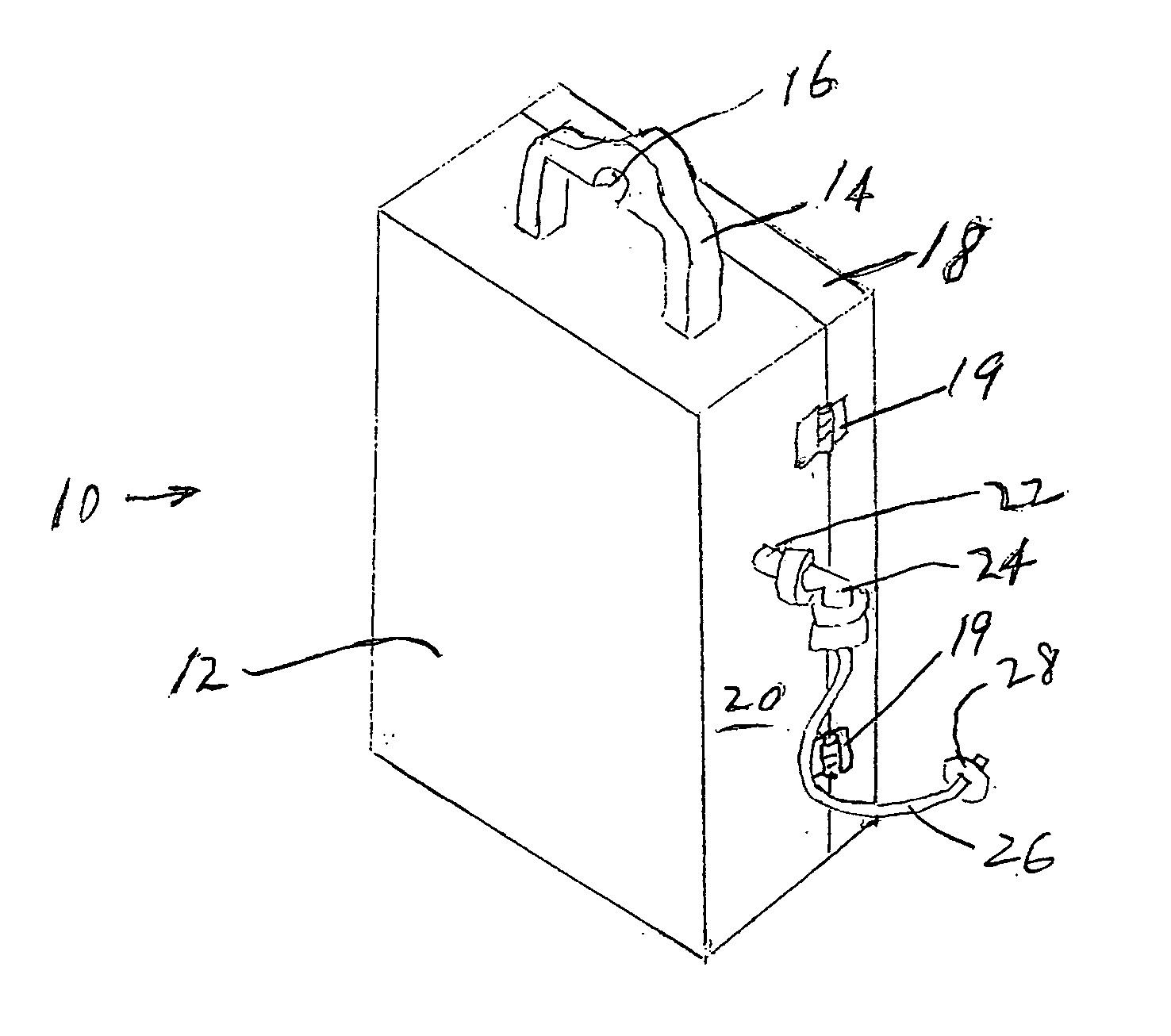
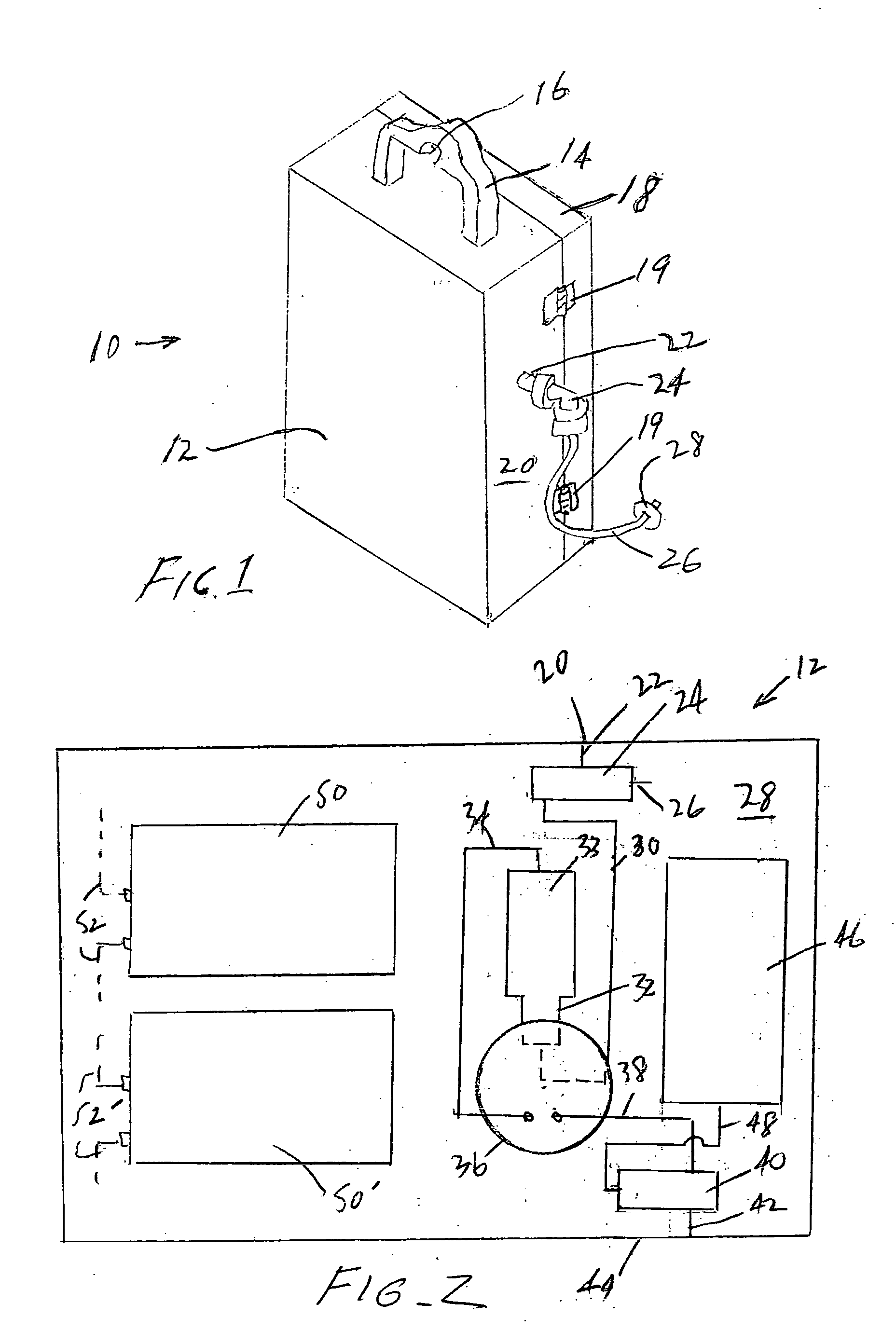
[0039]FIG. 1 is a prospective view of the invention 10. It includes a rectilinear, windowless housing having a rectangular footprint 12. It includes a carrying handle 14. Exposed at the top thereof is notch 16 allowing the inventive apparatus 10 to be suspended in a confin...


PUM

PropertyMeasurementUnit
timeaaaaaaaaaa
currentaaaaaaaaaa
concentrationaaaaaaaaaa

Abstract

Provided is an apparatus for gas sampling from a harsh environment which comprises a chemically resistant plastic housing suitable for suspension in a confined spacial environment. The housing has apertures for inlet and outlet tubes by which sampled air is drawn into and then discharged from the housing. Included are two three way valves to control selective fluid communication with the environment, a gas sensor, a filter selectively remove contamination from the housing and prevent saturation of the gas sensor, a pump disposed within the housing to effect selective fluid flow through the gas sensor and filter, and a power source that is preferably batteries. The apparatus electronics are all integrated into an electronics module configured so as to communicate with an external readout in a remote location via several methods. Sampling data is accumulated by a data logger which includes the capacity to retain such information as date and time of sampling, concentration of each sample, and the unit's identification data. The electronics module is in electrical communication with the power source. Power is also supplied to the pump and valves that control the admission of sample gas, direction of it to the sensor, discharge of gas to the harsh environment, and filtration of all the atmosphere within the housing to (1) flush the sensor and (2) clear contamination from the interior of the housing.

Description

BACKGROUND OF THE INVENTION [0001] 1. Field of the Invention [0002] The present invention generally relates to the field of remote continuing discrete monitoring of particular substances, and more particularly to a apparatus for the sensing of gases in harsh environments such as, but not limited to, hydrogen sulfide gas on a continuing discrete basis, and the communication of that information remotely. It also relates to the method of operation of that apparatus. [0003] 2. Description of the Prior Art [0004] Exposure to hazardous gases in confined spaces has been recognized as a major danger for many years for both personnel required to enter such spaces and the damaging effect the gases have on the equipment and materials exposed to the gases and their chemical byproducts. The latter condition is generally referred to herein as a harsh environment. [0005] Many devices have been developed to indicate the level of hazardous gases for the protection of individuals and equipment but th...

Claims


Application Information

Patent Timeline
Patent Type & Authority Applications(United States)
IPC IPC(8): G01N1/18G01N1/22G01N1/24G01N35/00
CPCG01N1/2273Y10T436/25375G01N35/00871G01N1/24
Inventor SCHUR, HENRY B.SCHUR, JENNIFERMORGAN, GARY
Owner GALAXY OPTOELECTRONICS
Why Eureka
Try Eureka