
Spiral centering catheter

a catheter and spiral technology, applied in the field of catheters, can solve the problems of narrow passageway, inability to treat lesion successfully, and irregular lumenal surface, and achieve the effect of avoiding adverse lumen contact, facilitating access to the lesion location, and facilitating passag

Inactive Publication Date: 2005-08-04
CARDINAL HEALTH SWITZERLAND 515 GMBH
View PDF40 Cites 46 Cited by
  • Summary
  • Abstract
  • Description
  • Claims
  • Application Information

AI Technical Summary

Benefits of technology

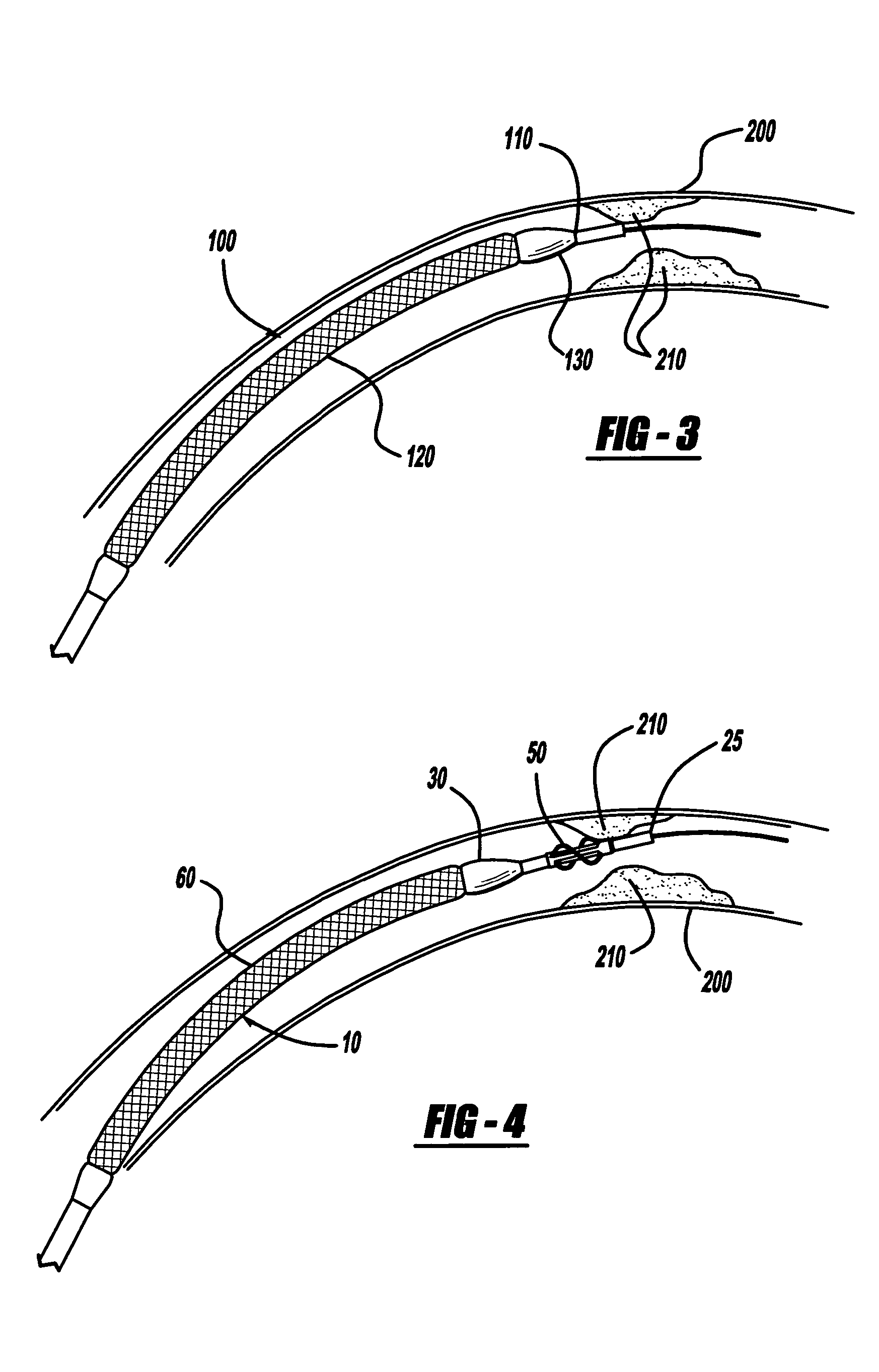
[0016] An advantage of the present invention is that the sometimes-tortuous anatomy of the vasculature may be more easily traversed while avoiding adverse lumen contact, and access to the lesion location may be facilitated by the availability of a spiral centering device that tends to center the distal portion of the catheter throughout its introduction into the vessel or other anatomy. Another advantage of the present invention is that the spiral centering device may stabilize the distal end of the catheter during stent expansion, and may therefore allow a physician to achieve a more uniform stent expansion with resultant clinical benefits to the patient.

Problems solved by technology

One commonly encountered challenge with the procedure involves irregularities of the lumenal surface and narrowing of the passageway, because the distal end of the balloon catheter or the stent delivery system may “catch” on the wall surface.
This may cause a challenge in reaching the desired position in the vessel, and therefore may inhibit successful treatment of the lesion.
Another difficulty that may be encountered with this procedure is that once the lesion is reached, stent deployment may not be perfectly uniform if the stent delivery system is not centered within the vessel, resulting in non-uniform deployment.
The end result may be reduced strength and incomplete stent scaffolding of the vessel, and a less than optimal clinical result.

Method used


Image

  • Spiral centering catheter
  • Spiral centering catheter
  • Spiral centering catheter

Examples


Embodiment Construction

[0024] The following description of the preferred embodiments of the present invention is merely illustrative in nature, and as such it does not limit in any way the present invention, its application, or uses. Numerous modifications may be made by those skilled in the art without departing from the true spirit and scope of the invention.

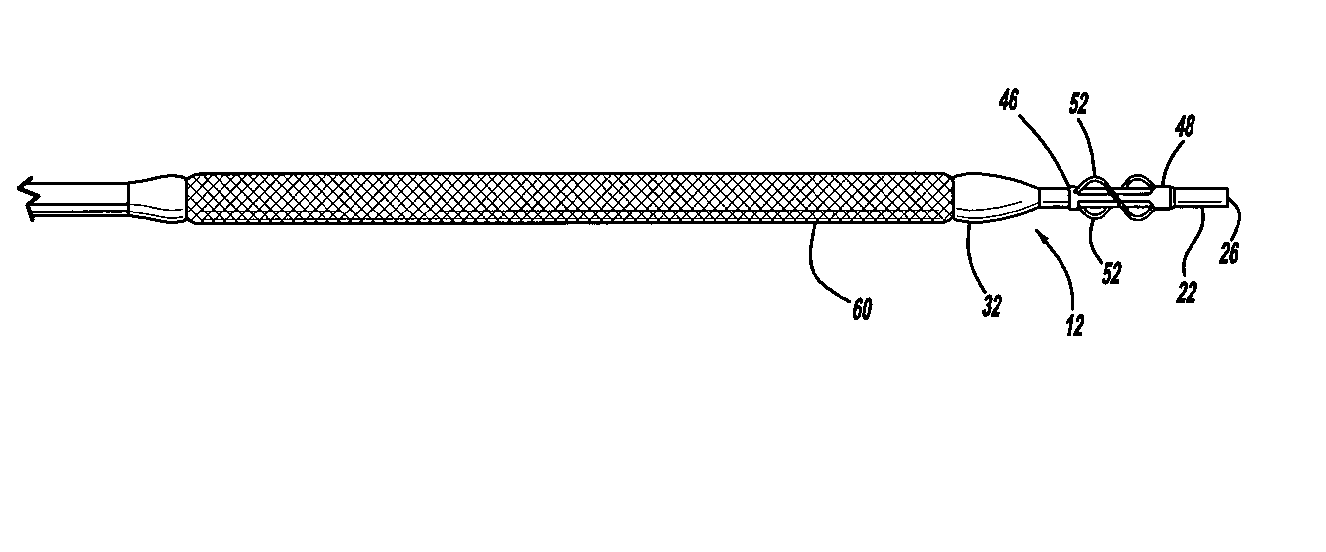
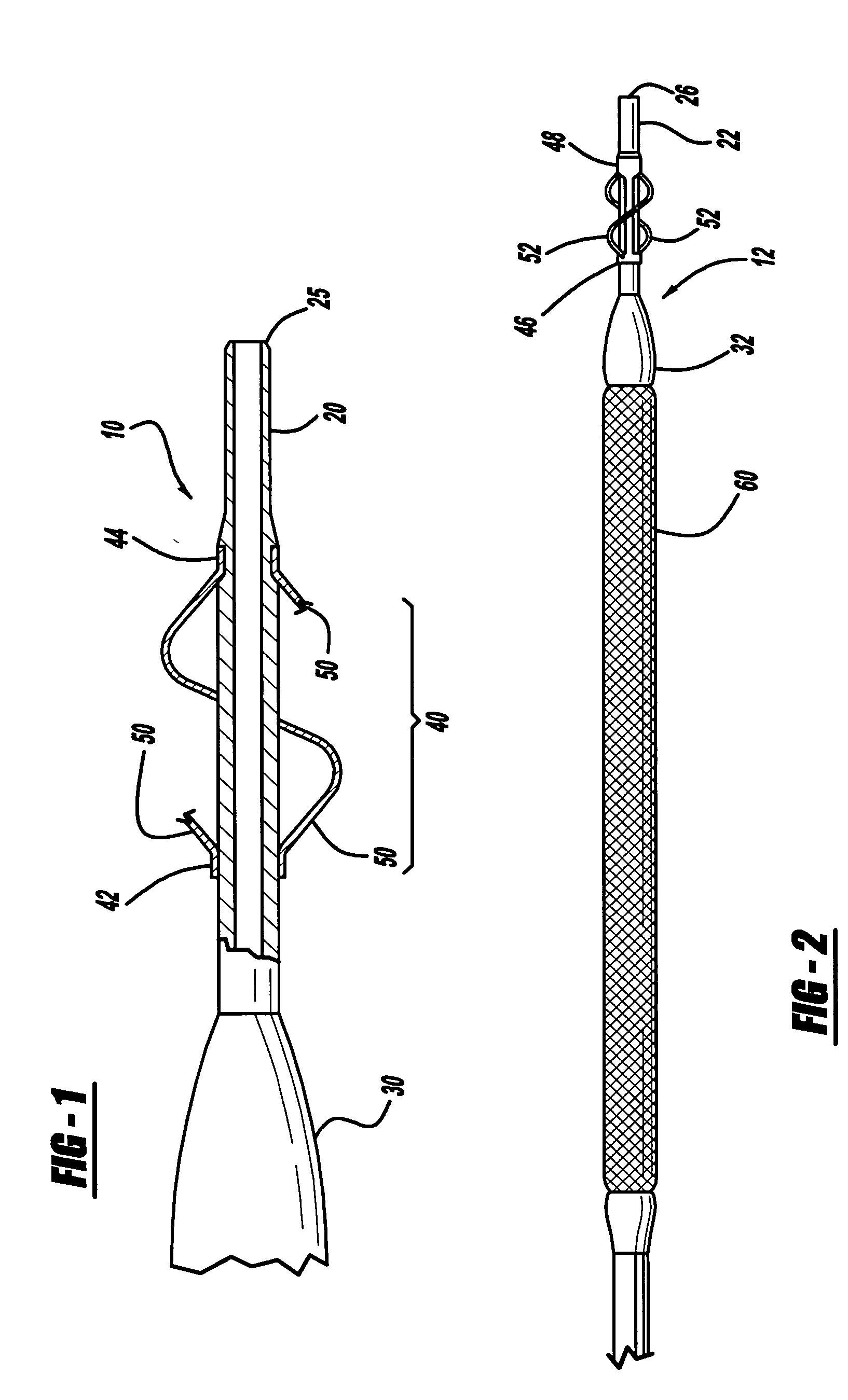
[0025] Centering catheters according to the principles of the present invention are designed to facilitate access to a treatment site in a lumen of a body passage through anatomy which may be tortuous, and / or to facilitate uniform stent deployment at a treatment site. A spiral centering catheter of the present invention may have an elongated catheter body with a proximal end and a distal end, and at least one spiral centering device attached near the distal end of the catheter. The spiral centering device may have a proximal end and a distal end, and at least one spiral strut extending therebetween. The spiral centering device has a smaller first s...


PUM


Abstract

A catheter with proximal and distal ends having a spiral centering device attached near the catheter distal end. The spiral centering device has at least one spiral strut having a proximal end and a distal end. The spiral centering device resiliently tends to center the distal end portion of the catheter, steering the catheter away from the vessel wall during insertion through the vasculature and toward the treatment site. The spiral centering catheter may facilitate access to tortuous anatomy by preventing the distal catheter tip from catching on irregularities in the lumenal surface. If a stent is provided on the catheter, the spiral centering catheter may also facilitate uniform stent expansion by stabilizing the catheter during stent deployment.

Description

CROSS-REFERENCE To RELATED APPLICATION [0001] The present application is a continuation-in-part of Ser. No. 10 / 178,434, entitled “Centering Catheter” filed Jun. 24, 2002.BACKGROUND AND SUMMARY OF THE INVENTION [0002] 1. Technical Background: [0003] The present invention relates to a catheter, and more particularly to a catheter with a spiral centering tip. [0004] 2. Discussion: [0005] Percutaneous transluminal coronary angioplasty (PTCA), percutaneous transluminal angioplasty (PTA), and stenting are therapeutic medical procedures used to increase blood flow through blood vessels, and can often be used as alternatives to coronary bypass surgery. In angioplasty procedures, a balloon is inflated within a narrowed or stenosed vessel, at a desired location for treatment, such as an atheroma or plaque deposit, in order to obtain an enlarged opening or lumen. In stenting, an endoluminal prosthesis of any appropriate type is implanted in the vessel to maintain patency and hold open the vess...

Claims


Application Information

Patent Timeline
IPC IPC(8): A61F2/90A61F2/958A61M25/00A61M25/10
CPCA61F2/958A61M2025/1047A61M25/0069A61M25/0043
Inventor MAJERCAK, DAVID C.
Owner CARDINAL HEALTH SWITZERLAND 515 GMBH
Learn More