

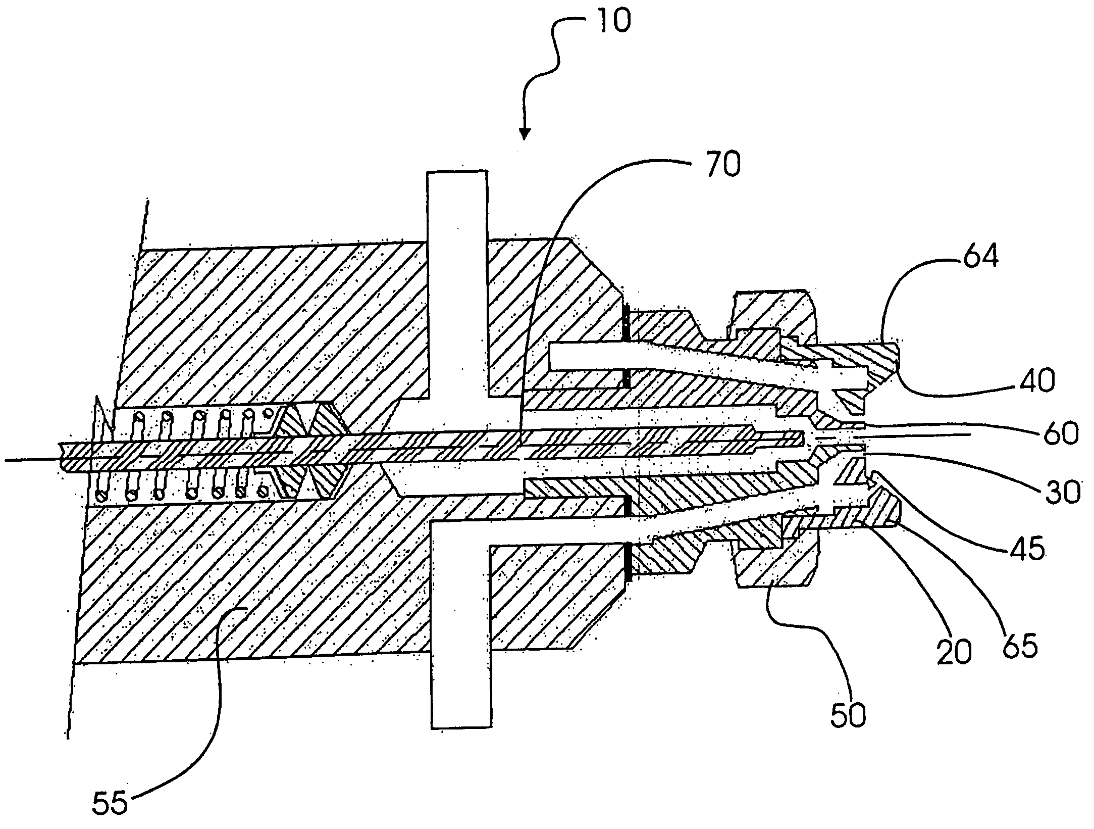
Spray nozzle assembly
a technology of spray nozzle and assembly, which is applied in the direction of spray nozzle, combustion process, lighting and heating apparatus, etc., can solve the problems of repeated downtime of cleaning equipment, rapid build-up of spray sprayed material on the surface of the nozzle, and poor performance, so as to reduce the amount of overspray and build-up, and the drop size is large
- Summary
- Abstract
- Description
- Claims
- Application Information
AI Technical Summary
Benefits of technology
Problems solved by technology
Method used
Image

Examples
example 3
[0093] Spray test using a spray nozzle having only an annular atomizing air flow.
[0094] This test employed spray nozzle assembly, nozzle cover and wind tunnel set-up of Example 2, except that the air cap was replaced with one having only a centrally-located circular orifice having a diameter of 0.173″. The base of the duckbill was secured between the air cap and the liquid cap. A retaining ring having four air holes evenly distributed about its perimeter was positioned between the base of the duckbill and the air cap to secure the duckbill in position. The holes in the retaining ring permitted air to pass through to the circular orifice of the air cap. The front end of the duckbill protruded out of the centrally-located circular orifice of the air cap and an annular orifice (0.25 wide) formed around the periphery of the duckbill. The air flow emitted through the annular opening was substantially parallel to the flow of liquid emitted from the duckbill. The spray nozzle assembly is ...
example 4
Spray Test Using a Spray Nozzle Having Separate Atomizing and Fanning Air Flows and Using a Duckbill Valve.
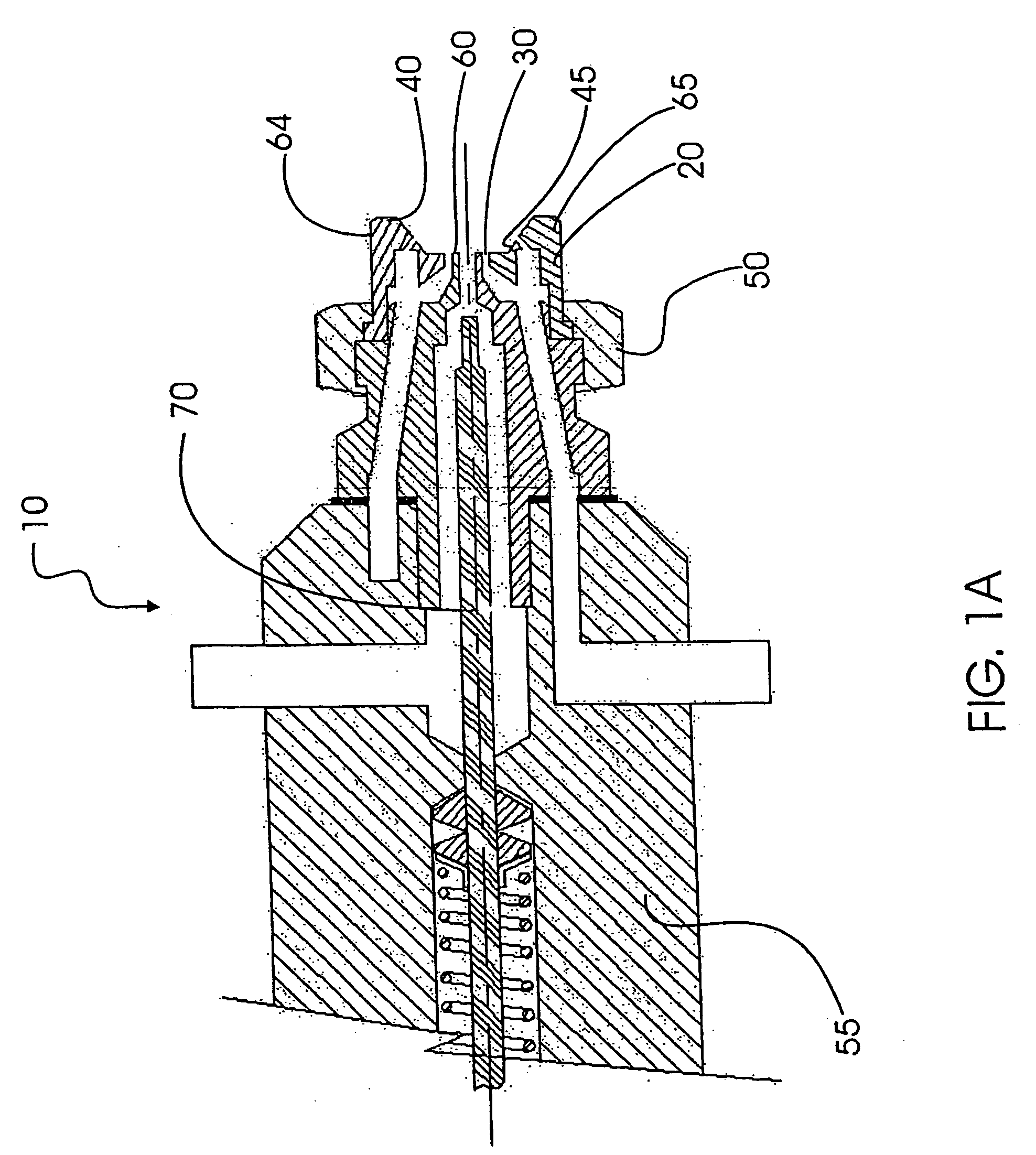
[0096] This test employed spray nozzle assembly, nozzle cover and wind tunnel set-up of Example 2, except that that the centrally located circular orifice of the air cap was enlarged to a diameter of 4.39 mm (0.173 inch). The front end of the duckbill protruded out of the centrally-located circular orifice of the air cap and an annular orifice (0.25 mm wide) formed around the periphery of the duckbill. The air flow emitted through the annular opening was substantially parallel to the flow of liquid emitted from the duckbill. The spray nozzle assembly is shown in FIG. 2B.
[0097] The test was run for 8 hour using a spray rate of 0.1 L / mile at a train speed of 30 km / hr. in a wind speed of 30 km / hr, and an air pressure setting of 40 psi. After this test was completed, coverage of the air cap was about 20-30% of the amount of coverage observed from the results of Example 2, and th...
example 5
Spray Test Using a Spray Nozzle Providing an Atomizing Air Flow From Six Evenly Spaced Circular Openings.
[0098] This test employed the spray nozzle assembly, nozzle cover and wind tunnel set-up of Example 2, except that the air cap was replaced with a cap having six circular openings (each having a diameter of 3 / 64″) provided in a circular arrangement, concentric with a centrally-located circular orifice having a diameter of 3.89 mm (0.153 inch). The center of each circular opening was 3.5 mm from the center of the air cap. The base of the duckbill was secured between the air cap and the liquid cap. The front end of the duckbill protruded out of the centrally-located circular orifice of the air cap and occupied the entire area of the orifice, so that only liquid could be emitted from the center of the air cap. The air cap of the spray nozzle assembly is shown in FIG. 2C. Each of the circular openings provided an air flow that was substantially parallel to the flow of liquid emitte...
PUM
 Abstract
Description
Claims
Application Information