One wire self referencing circuits for providing power and data

a self-referencing circuit and wire technology, applied in the field of electrical devices, can solve problems such as inability to construct, and achieve the effect of dissipating energy already and improving design efficiency

Inactive Publication Date: 2005-08-11
LYNK LABS INC
View PDF22 Cites 41 Cited by
  • Summary
  • Abstract
  • Description
  • Claims
  • Application Information

AI Technical Summary

Benefits of technology

[0003] The self reference one wire method and device goes one step ahead. For low power light applications and for signal applications there are benefits in using the single wire as a reference voltage without the need to bring extra objects to dissipate the energy already in place. With precautions to protect integrated circuits and low power electronic devic

Problems solved by technology

For portable devices this is a good thing, ot

Method used


Image

  • One wire self referencing circuits for providing power and data
  • One wire self referencing circuits for providing power and data
  • One wire self referencing circuits for providing power and data

Examples


Embodiment Construction

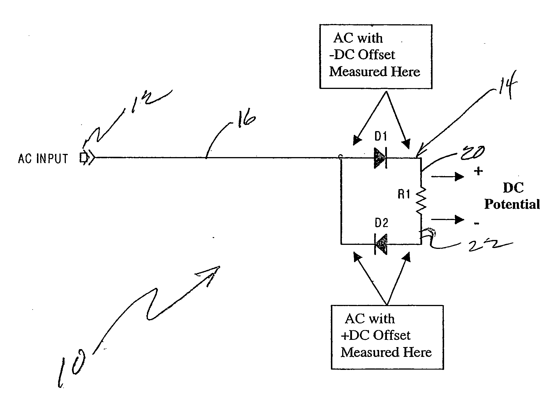
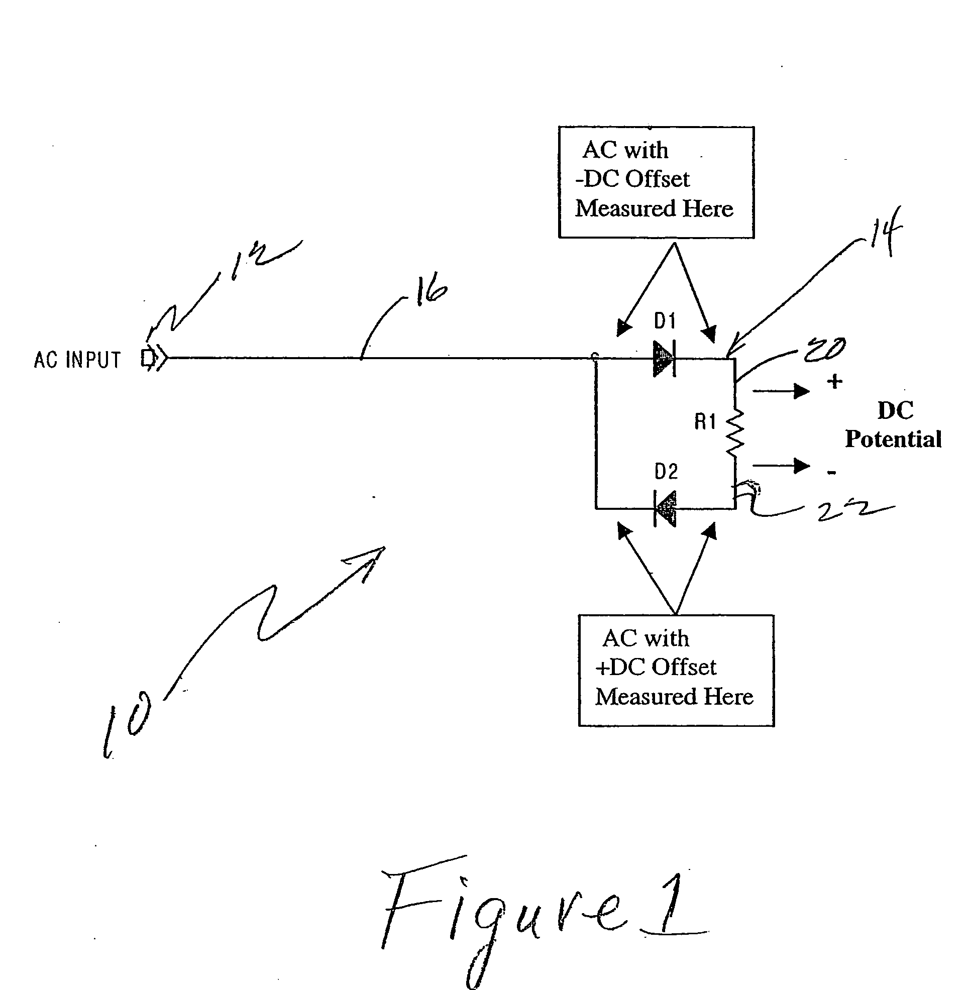
[0022]FIG. 1 discloses a preferred circuit 10 according to the invention. The circuit 10 includes a first source for providing an alternating electric field. The source maybe the output of a standard AC signal generator such as generator 12 of FIG. 1. This generator 12 may produce its signal with reference to ground as indicated in FIG. 1. Circuit 10 also discloses a directional circuit 14 connected to the generator 12 by a transmission conductor 16. According to the invention the conductor 16 may be any form of conventional conductive path whether twisted wire bundles, single wires, etc. The point is that the transmission conductor 16 provides a single transmission path to the directional circuit 14. Important to the invention is the fact that there is no conductive return path provided back from the directional circuit 16 to the generator 12.

[0023] In the broad sense, the directional circuit 14 is loop circuit which includes one or more circuit elements causing the loop circuit t...


PUM


Abstract

A circuit includes a first source for providing an alternating electric field, a directional circuit connected to the first source for providing an alternating electric field by a transmission conductor there being no conductive return path provided back from the directional circuit to the first source for providing an alternating electric field. The directional circuit being a loop circuit which includes one or more circuit elements causing the loop circuit to be asymmetric to current flow; the directional circuit having no continuous connective path to earth ground, or battery ground, the directional circuit thereby developing a DC potential in response to the alternating electric field which is self referencing between a relatively high potential output and a relatively lower potential output. One or more loads connected to the directional circuit, the one or more loads also not having a continuous conductive path to earth ground or a battery ground. The load is not provided with a continuous connection to earth ground, or battery ground.

Description

TECHNICAL FIELD [0001] The present application relates generally to the field of electronics and more particularly to circuits and methods for providing power or data transmission at relatively low power and relatively high frequency. BACKGROUND AND SUMMARY OF THE INVENTION [0002] This invention continues the line of inventions of Nikola Tesla, and Stanislav and Konstantin Avramenko. It is possible to transfer power through one wire, even to operate an electric motor. For the field of electric light, it is also possible to transfer power without any wires. [0003] The self reference one wire method and device goes one step ahead. For low power light applications and for signal applications there are benefits in using the single wire as a reference voltage without the need to bring extra objects to dissipate the energy already in place. With precautions to protect integrated circuits and low power electronic devices, it is possible to design efficient systems when the energy and the e...

Claims


Application Information

Patent Timeline
IPC IPC(8): G06FH02J1/00H02J3/00H02J17/00
CPCH02J17/00H02J1/00H02J1/06H02J50/005H02J5/00
Inventor ANDERSEN, JAMES N.CANTORAL, EDUARDOMISKIN, MICHAEL
Owner LYNK LABS INC
Why Eureka
Try Eureka