Current-perpendicular-to-plane magnetoresistive sensor with free layer stabilized against vortex magnetic domains generated by the sense current

a technology of magnetoresistive sensor and free layer, applied in the field of current perpendicular to the plane (cpp) magnetoresistive sensor, can solve the problems of undesirable sensor self biasing and undesirable optical field

Inactive Publication Date: 2005-08-11
HITACHI GLOBAL STORAGE TECH NETHERLANDS BV
View PDF3 Cites 38 Cited by
  • Summary
  • Abstract
  • Description
  • Claims
  • Application Information

AI Technical Summary

Benefits of technology

[0008] In operation of the CPP sensor, the sense current generates a vortex magnetic field in the free layer in a generally circular direction opposite to the direction of the fixed vortex magnetization pattern in the stabilizing layer. This sense-current-generated field essentially counteracts the vortex magnetization pattern and essentially “erases” the effect of the vortex magnetization pattern in the free layer. The result is that the preferred single-domain longitudinal magnetization in the free layer is not adversely affected, and the free layer can respond to the magnetic transitions on the recording medium as substantially a single magnetic domain.

Problems solved by technology

The Oersted field is undesirable because it tends to cause a vortex or other non-longitudinal magnetization pattern inside the free layer for high current densities.
In the case of an asymmetric current density distribution through the free layer, the Oersted field may cause a highly non-uniform domain state, which results in undesirable self biasing of the sensor.

Method used


Image

  • Current-perpendicular-to-plane magnetoresistive sensor with free layer stabilized against vortex magnetic domains generated by the sense current
  • Current-perpendicular-to-plane magnetoresistive sensor with free layer stabilized against vortex magnetic domains generated by the sense current
  • Current-perpendicular-to-plane magnetoresistive sensor with free layer stabilized against vortex magnetic domains generated by the sense current

Examples


Embodiment Construction

Prior Art

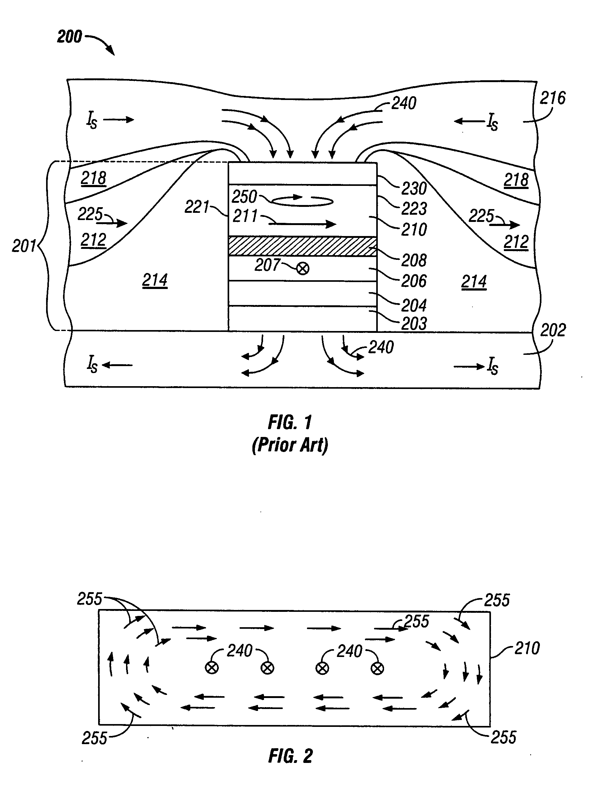
[0015]FIG. 1 is a sectional view of a prior art CPP sensor 200. Sensor 200 comprises a stack 201 of layers formed on a substrate 202, which in the case of a read head is the bottom magnetic shield that also serves as the bottom electrical lead. A top magnetic shield 216 on stack 201 also serves as the top electrical lead. The layers in stack 201 include a pinned ferromagnetic layer 206 having a fixed magnetic moment or magnetization direction 207 oriented transversely (into the page), a free ferromagnetic layer 210 having a magnetic moment or magnetization vector 211 that can rotate in the plane of layer 210 in response to transverse external magnetic fields, and a nonmagnetic spacer layer 208 between the pinned layer 206 and free layer 210. The pinned layer 206 is exchange coupled with an antiferromagnetic layer 204 that is formed on a suitable seed layer or underlayer 203 on substrate 202. Thus the magnetization direction 207 of pinned layer 206 is fixed and will not ro...


PUM

PropertyMeasurementUnit
thickaaaaaaaaaa
thickaaaaaaaaaa
magneticaaaaaaaaaa

Abstract

A current-perpendicular-to-the-plane (CPP) magnetoresistive sensor has additional layers for stabilizing the free layer against sense-current-generated magnetic fields. A ferromagnetic stabilizing layer is spaced from the free layer by a spacer layer and is exchange coupled with a second antiferromagnetic layer, the first antiferromagnetic layer being the conventional one for pinning the pinned layer in the CPP sensor. The stabilizing layer is in a vortex or other non-longitudinal magnetization pattern that is fixed by exchange coupling with the second antiferromagnetic layer. The stabilizing layer is also ferromagnetically coupled to the free layer across the spacer layer so that in the absence of both a sense current and an external magnetic field, the free and stabilization layers have similarly shaped vortex or other non-longitudinal magnetization patterns. The sense current generates a vortex magnetic field in the free layer opposite to the fixed vortex magnetization pattern in the stabilizing layer and essentially erases the effect of the vortex magnetization pattern in the free layer.

Description

TECHNICAL FIELD [0001] The invention relates to a current-perpendicular-to-the-plane (CPP) magnetoresistive sensor that operates with the sense current directed perpendicularly to the planes of the layers making up the sensor stack. BACKGROUND OF THE INVENTION [0002] One type of conventional magnetoresistive sensor, often called a “spin-valve” (SV) sensor, has a stack of layers that include two ferromagnetic layers separated by a nonmagnetic spacer layer. One ferromagnetic layer has its magnetization direction fixed, such as by being pinned by exchange coupling with an adjacent antiferromagnetic layer, and the other ferromagnetic layer has its magnetization direction “free” to rotate in the presence of an external magnetic field. With a sense current applied to the sensor, the rotation of the free-layer magnetization relative to the fixed-layer magnetization is detectable as a change in electrical resistance. The SV type of magnetoresistive sensor typically operates with the sense c...

Claims


Application Information

Patent Timeline
Patent Type & Authority Applications(United States)
IPC IPC(8): G11B5/39G01R33/09G11B5/127G11B5/33H01F10/06H01F41/14H01L43/08H01L43/12
CPCG11B5/39G11B5/1278
Inventor KASIRAJ, PRAKASHMAAT, STEFAN
Owner HITACHI GLOBAL STORAGE TECH NETHERLANDS BV
Why Eureka
Try Eureka