Underwater light

a technology of underwater lights and wire coupling, which is applied in the direction of coupling device connections, lighting and heating apparatus, lighting applications, etc., can solve the problems of difficult and expensive replacement of bulbs, installation and maintenance of prior art underwater lights, etc., and achieves simple yet effective coupling methods. simple and convenient installation, the effect of reducing the cost of replacemen

Inactive Publication Date: 2005-08-11
LUNT GARY W
View PDF11 Cites 6 Cited by
  • Summary
  • Abstract
  • Description
  • Claims
  • Application Information

AI Technical Summary

Benefits of technology

[0005] This invention addresses the need of an underwater lighting system that is easily installed and inexpensively repaired by the consumer. Other systems advertise the need of the installation and the factory replacement of the lamp by trained individuals. The replacement of the lamp in this system is easily done by anyone familiar with the use of a soldering gun. Unlike other systems using a mogul socket or porcelain lamp holder, made by such manufacturers as Philips, to couple the lamp electrically to the wires, none is needed or used in this system. A simple yet very effective method of coupling the wires to the lamp is done by soldering, eliminating one component prone to failure.
[0006] This underwater lighting system can be easily placed in the water, which is typically a canal and be easily retrieved with minimal effort. Curr

Problems solved by technology

There are problems with installing and maintaining prior art underwater lights.
As a general rule, when the bulb of a prior a

Method used


Image

  • Underwater light
  • Underwater light
  • Underwater light

Examples


Embodiment Construction

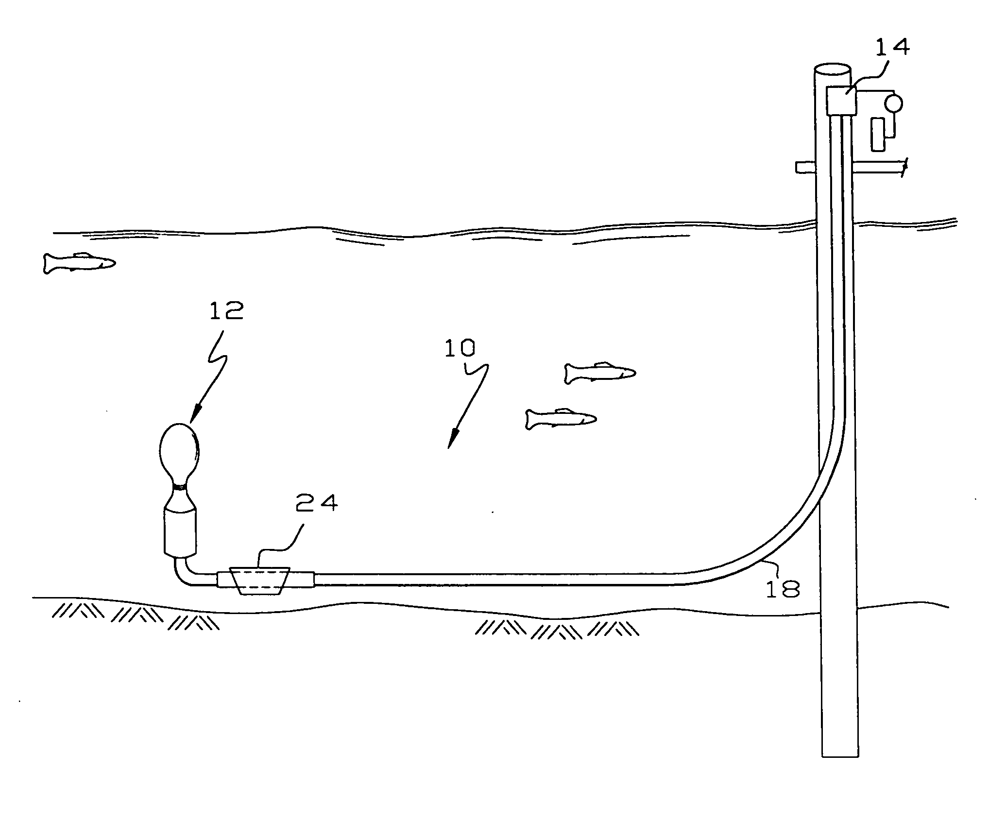
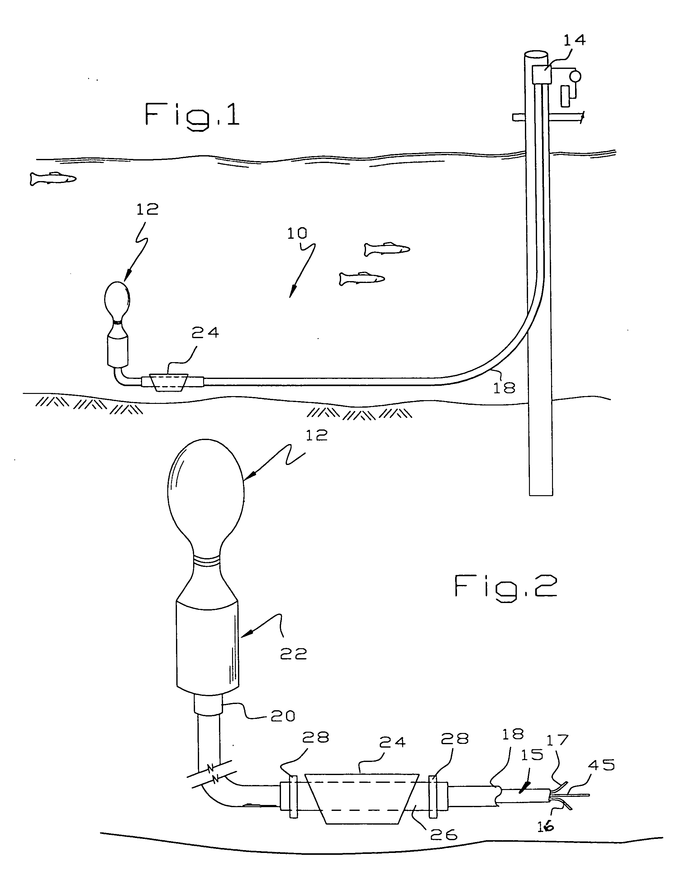
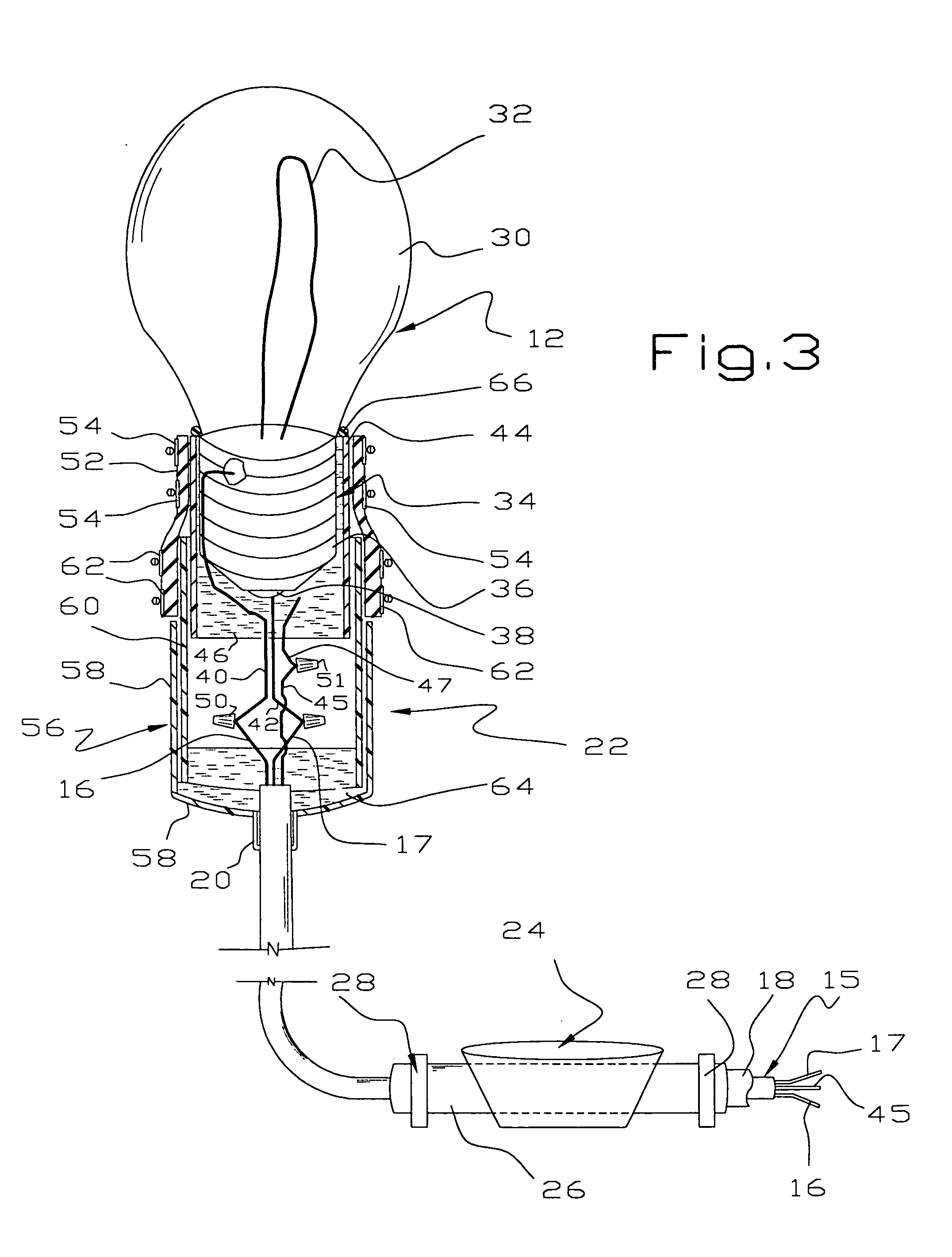
[0011] Referring to FIGS. 1-3, the underwater light 10 of this invention comprises a lamp 12 electrically coupled to a transformer 14 by a pair of suitable insulated wires 16, 17 being part of an insulated three wire assembly 15 received in and protected by a flexible conduit 18. Currently the preferred lamp 12 is a mercury vapor lamp, although any high intensity lamp may be used. Mercury vapor lamps have been used successfully by numerous builders of underwater lighting systems since the early to mid 1990's. The transformer 14 is controlled by a photoelectric eye (not shown) that automatically turns the light on at night and off at daybreak. The transformer 14 is coupled to an electrical source on shore using a ground fault circuit interrupter to meet electrical code requirements.

[0012]FIG. 2 shows a high profile model used when water depth is greater than 7 feet. The flexible conduit 18 is coupled directly to a PVC nipple 20 of a lamp enclosure 22. Lamps have been successfully pl...


PUM


Abstract

An underwater light includes a high intensity lamp placed in an enclosure that allows for easy lamp replacement in case of breakage or natural failure. Electrical wires are soldered to a metal fitting on the lamp. The metal fitting is received in a plastic nipple and the space between the fitting and nipple is filled with a sealant, leaving the ends of the wires exposed. The wires are connected by water proof wire nuts and the end of the lamp is enclosed by a rubber boot and an end cap. When the lamp burns out, it is easily replaced by fishing the light out of the water, removing the rubber boot to expose the wire nuts. The wire nuts are removed and the old lamp discarded. A new lamp is installed in reverse order.

Description

[0001] This invention relates to an underwater light, and more particularly to an underwater light which is easy to install and which is easy to replace the bulb. BACKGROUND OF THE INVENTION [0002] Underwater light sources have been installed for many years in order to illuminate canals in housing developments. These lights attract fish, provide illumination and generally are attractive. [0003] There are problems with installing and maintaining prior art underwater lights. As a general rule, when the bulb of a prior art underwater light burns out, it is difficult and expensive to replace the bulb because of the construction of the assembly. [0004] Underwater light assemblies are known in the prior art, such as in U.S. Pat. Nos. 1,745,901; 3,005,908; 3,946,263; 4,598,346 and 6,315,429 and printed application 2002 / 0178641. Of more general interest are U.S. Pat. Nos. 4,500,151 and 4,869,683. SUMMARY OF THE INVENTION [0005] This invention addresses the need of an underwater lighting sys...

Claims


Application Information

Patent Timeline
IPC IPC(8): F21S8/00F21V19/04F21V33/00H01R13/52H01R33/965
CPCF21S8/00F21V19/04H01R33/9651H01R13/5216F21W2131/401
Inventor LUNT, GARY W.
Owner LUNT GARY W
Why Eureka
Try Eureka