Liquid medicine supplying device and method for venting air from liquid medicine supplying device

a technology of liquid medicine and supplying device, which is applied in the direction of liquid degasification, separation processes, instruments, etc., can solve the problems of difficult stably dispense of chemical liquid, inability to remove completely the bubbles collected in the filter filtration film, and difficulty in stabilizing so as to improve remarkably the dispense accuracy and stabilize the amount of chemical liquid. , the effect of high quality

Inactive Publication Date: 2005-08-11
KOGANEI
View PDF70 Cites 29 Cited by
  • Summary
  • Abstract
  • Description
  • Claims
  • Application Information

AI Technical Summary

Benefits of technology

[0007] An object of the present invention is to stabilize the amount of chemical liquid dispensed from the chemical liquid supply apparatus and to improve remarkably the dispense accuracy.
[0008] Another object of the present invention is to manufacture semiconductor integrated circuits with high quality and good yield.

Problems solved by technology

However, in such a conventional chemical liquid supply apparatus, it has become clear to be unable to remove completely the bubbles collected in a filtration film of the filter due to matter such as flow resistance of the filtration film, and osmotic pressure of the chemical liquid.
As far as the bubbles cannot be exhausted completely from the inside of the filtration film of the filter, it is difficult to dispense stably the chemical liquid and improve the dispense accuracy.
Accordingly, the improved manufacture yield of products is not expected.

Method used


Image

  • Liquid medicine supplying device and method for venting air from liquid medicine supplying device
  • Liquid medicine supplying device and method for venting air from liquid medicine supplying device
  • Liquid medicine supplying device and method for venting air from liquid medicine supplying device

Examples


Embodiment Construction

[0025] Hereinafter, embodiments of the present invention will be detailed based on the drawings.

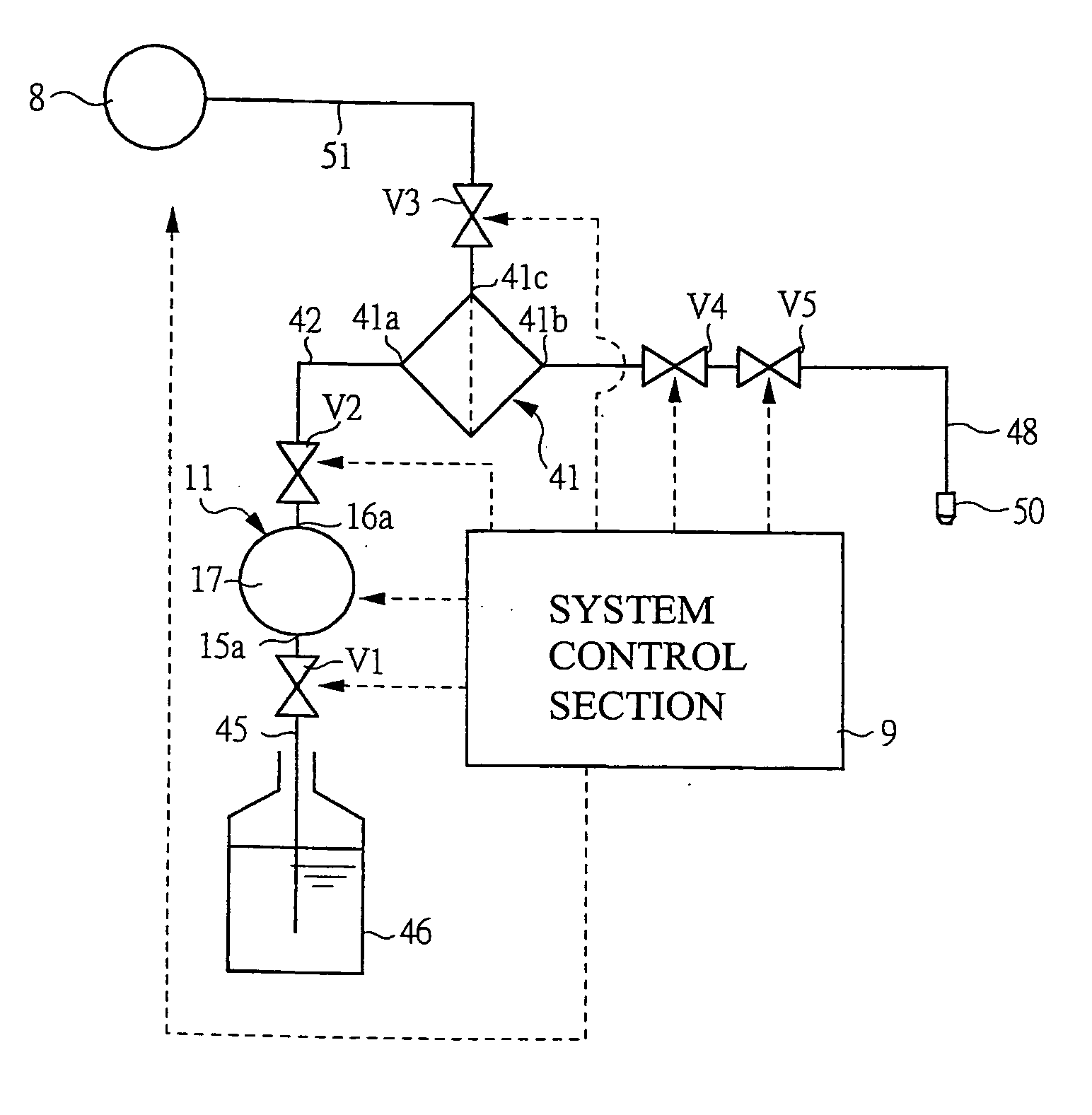
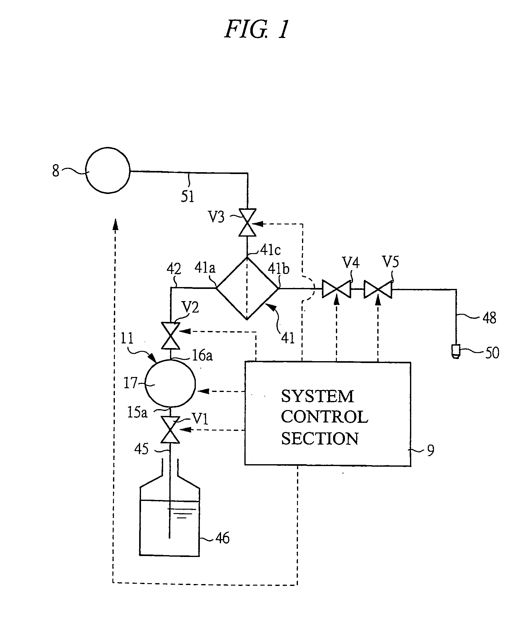
[0026]FIG. 1 is a liquid circuit diagram showing schematically a chemical liquid supply apparatus according to an embodiment of the present invention. As shown in FIG. 1, the chemical liquid supply apparatus comprises: a pump 11 for discharging a liquid accommodated in a liquid tank 46; a filter 41 connected to the pump 11 through a pump outlet flow path 42 to which a pump discharge-side valve V2 for opening / closing the flow path is provided; a dispensing nozzle (liquid dispense portion) 50 connected to the filter 41 through a liquid discharge flow path 48 to which a discharge valve V4 for opening / closing the flow path is provided; and a vacuum source 8 communicating with the filter 41 through an exhaust flow path 51 to which a deaeration valve V3 for opening / closing the flow path is provided. The structure of the chemical liquid supply apparatus and its components such as the pump 11, t...


PUM

PropertyMeasurementUnit
chemical liquidaaaaaaaaaa
pressureaaaaaaaaaa
discharge pressureaaaaaaaaaa

Abstract

The amount of chemical liquids dispensed by a chemical liquid supply apparatus is stabilized and dispensing accuracy is remarkably improved. A pump discharges a liquid accommodated in a liquid tank. A filter is connected to the pump through a pump outlet flow path to which a pump discharge-side valve for opening / closing the flow path is provided. A dispensing nozzle (liquid dispense portion) is connected to the filter through a liquid discharge flow path to which a discharge valve for opening / closing the flow path is provided. A vacuum source communicates with the filter through an exhaust flow path to which a deaeration valve for opening / closing the flow path is provided.

Description

TECHNICAL FILED OF THE INVENTION [0001] The present invention relates to a chemical liquid supply apparatus for discharging a predetermined amount of liquids such as chemical liquids and, for example, to a chemical liquid supply apparatus and a deaerating method thereof, which are suitably used for coating a photoresist liquid on a surface of a semiconductor wafer. BACKGROUND OF THE INVENTION [0002] In each manufacturing process of various kinds of technical fields such as a semiconductor wafer manufacturing technique, a liquid crystal display manufacturing technique, a magnetic disk manufacturing technique, and a multilayer printed circuit board manufacturing technique, there has been used a chemical liquid such as a photoresist liquid, spin-on glass liquid, polyimide resin liquid, purified water, developer, etchant, cleaning liquid, or organic solvent, and a chemical liquid supply apparatus is used for coating such chemical liquid. For example, as such, a chemical liquid supply ap...

Claims


Application Information

Patent Timeline
Patent Type & Authority Applications(United States)
IPC IPC(8): B01D19/00B01J4/00B05C11/10F04B53/06G03F7/16G03F7/30G03F7/40G03F7/42H01L21/027
CPCB01D19/0031B01D19/0068G03F7/16G03F7/422G03F7/3021G03F7/40G03F7/162
Inventor UDAGAWA, SEIICHIRO
Owner KOGANEI
Why Eureka
Try Eureka