Vacuum thermal insulating material, process for producing the same and refrigerator including the same

a technology of thermal insulation material and vacuum heat, which is applied in the direction of heat insulation for cooling apparatus, domestic cooling apparatus, lighting and heating apparatus, etc., can solve the problems of inability to apply measures and urgent problems for domestic electric appliances

Inactive Publication Date: 2005-08-11
PANASONIC CORP
View PDF6 Cites 90 Cited by
  • Summary
  • Abstract
  • Description
  • Claims
  • Application Information

AI Technical Summary

Problems solved by technology

In recent years, energy saving has been strongly demanded from the viewpoint of prevention of global warming, and energy saving for domestic electric appliances has become an urgent probl...

Method used


Image

  • Vacuum thermal insulating material, process for producing the same and refrigerator including the same
  • Vacuum thermal insulating material, process for producing the same and refrigerator including the same
  • Vacuum thermal insulating material, process for producing the same and refrigerator including the same

Examples


first exemplary embodiment

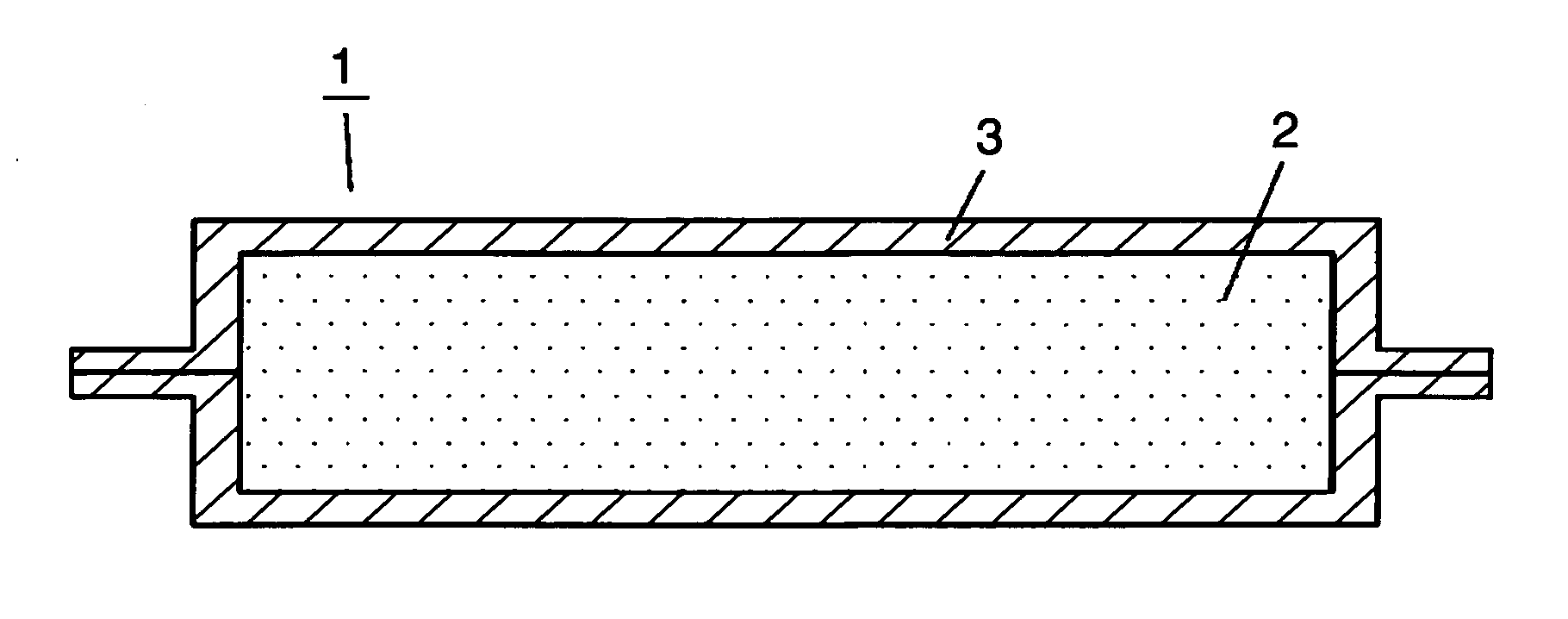
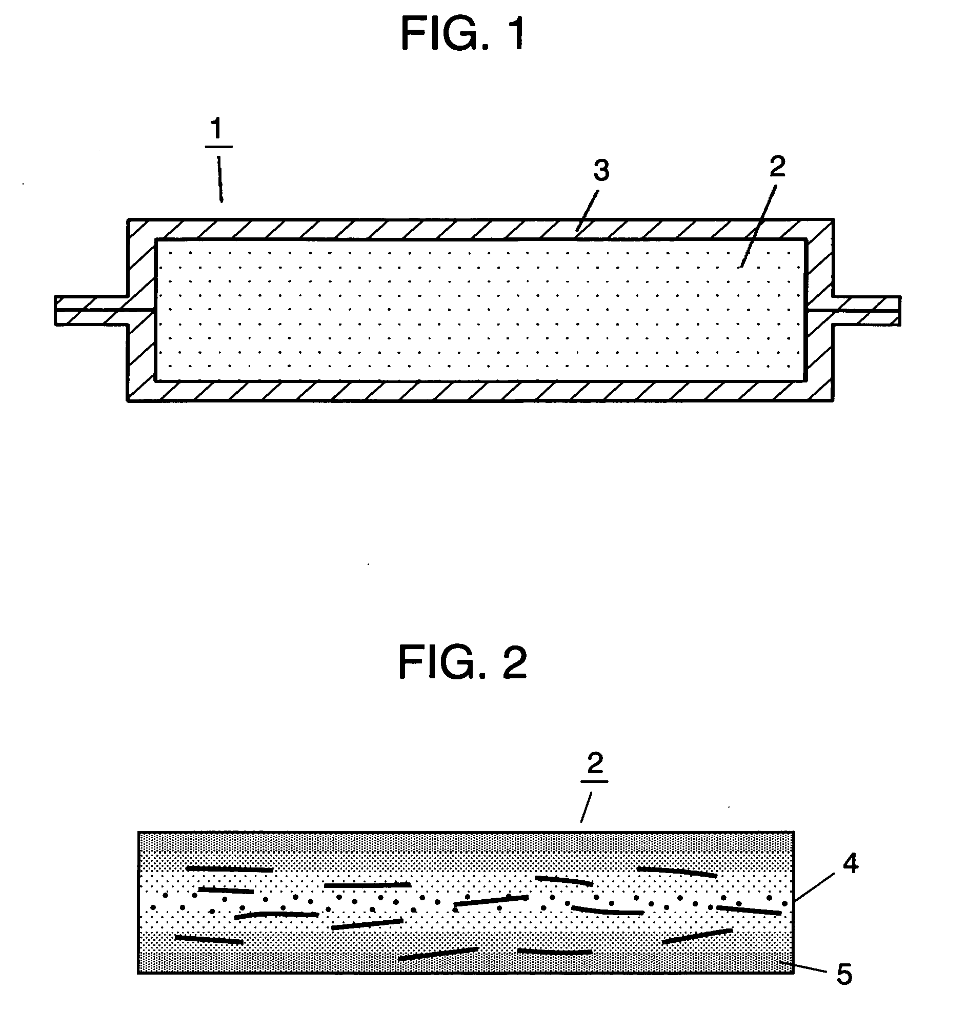
[0024]FIG. 1 is a cross sectional view showing a vacuum heat insulator according to a first exemplary embodiment of the present invention. Vacuum heat insulator 1 according to this embodiment includes core 2 and exterior covering 3 covering the same. Exterior covering 3 includes a gas-barrier film having a gas-barrier layer and a thermal fusing layer. An interior of exterior covering 3 is reduced in pressure. An opening of exterior covering 3 is thermally fused. Core 2 is formed by curing an inorganic fiber aggregate, which is laminated by a dry process to have an average fiber diameter of 5 μm, by means of a binding agent to make the same plate-shaped.

[0025] A method of manufacturing vacuum heat insulator 1 will be simply described below. After core 2 is dried at 140° C. for one hour, it is inserted into exterior covering 3. After an interior of exterior covering 3 is reduced to 13.3 Pa in pressure, its opening is bonded by thermal fusing.

[0026] The adiabatic performance (thermal...

second exemplary embodiment

[0049] Vacuum heat insulator 1 according to this embodiment is the same in fundamental constitution as that of the first exemplary embodiment shown in FIG. 1. This embodiment is different from the first exemplary embodiment in the structure of core 2. Core 2 in this embodiment is formed by coating an inorganic fiber aggregate which is laminated by the dry process to have an average fiber diameter of 7 μM, with a solid component of a phenol resin of 10 wt % as a binding agent and curing the same to make the same plate-shaped.

[0050] The adiabatic performance (thermal conductivity) of vacuum heat insulator 1 fabricated in this manner is measured at an average temperature 24° C. to be 0.0041 W / mK. Curing is adequately achieved since addition of the binding agent is 10 wt %. Since a decreasing rate of the thickness of core 2 due to reduction in pressure becomes 6%, atmospheric compression is small when vacuum heat insulator 1 is made, and the dimensional stability is sharply improved.

[...

third exemplary embodiment

[0055] Vacuum heat insulator 1 according to a third exemplary embodiment is the same in fundamental constitution as that of the first exemplary embodiment shown in FIG. 1. This embodiment is different from the first exemplary embodiment in the structure of core 2. Core 2 in this embodiment is formed by coating an inorganic fiber aggregate which is laminated by the dry process to have an average fiber diameter of 0.8 μm, with a phenol resin of 10 wt % as a solid component and curing the same to make the same plate-shaped.

[0056] The adiabatic performance (thermal conductivity) of vacuum heat insulator 1 fabricated in this manner is measured at an average temperature 24° C. to be 0.0024 W / mK. Curing is adequately achieved since addition of the binding agent is 10 wt %. Since a decreasing rate of the thickness of core 2 due to reduction in pressure is 5%, atmospheric compression is small when vacuum heat insulator 1 is made, and the dimensional stability is sharply improved.

[0057] Cor...


PUM


Abstract

A vacuum heat insulator according to the present invention includes a core molded to be plate-shaped with the use of a binding agent. The vacuum heat insulator assumes any one of the following configurations. A) The core is formed by curing a fiber aggregate by means of a binding agent. The fibers have an average fiber diameter of at least 0.1 μm but at most 10 μm, and voids defined by fibers have a void diameter of at most 40 μm. The core has a percentage of the voids of at least 80%. B) The binding agent is varied in concentration in a through-thickness direction of the core. C) A cured layer solidified by the binding agent is formed on at least one side surface of the core. D) The core contains fibers having a length of at most 100 μm. The fibers are oriented perpendicular to a direction of heat transmission. Such vacuum heat insulator is excellent in adiabatic property. Refrigerators, to which such a vacuum heat insulator is applied, are made small in size, or have a large inner volume, or contribute to energy saving.

Description

TECHNICAL FIELD [0001] The present invention relates to a vacuum heat insulator using a core formed to be plate-shaped, an adiabatic body, an adiabatic box body, an adiabatic door, a storage house, and a refrigerator, to which the vacuum heat insulator is applied, a method of manufacturing the vacuum heat insulator, and a method of manufacturing the core for the vacuum heat insulator. BACKGROUND ART [0002] In recent years, energy saving has been strongly demanded from the viewpoint of prevention of global warming, and energy saving for domestic electric appliances has become an urgent problem. In particular, heat insulators having an excellent adiabatic performance (heat insulating efficiency) are demanded for thermally insulated equipments such as refrigerators, freezers, automatic vending machines, etc. from the viewpoint of efficient use of heat. [0003] As general heat insulators, fiber materials such as glass wool, etc. and foam such as urethane foam, etc. are used. In order to ...

Claims


Application Information

Patent Timeline
IPC IPC(8): F16L59/06F16L59/065F25D23/06
CPCF16L59/065F25D23/065Y10T428/231F25D2201/14F25D2500/02F25D2201/12
Inventor HIRAI, YOSHIHIDEHIRAI, CHIETANIMOTO, YASUAKITSUNETSUGU, KEISUKENAKAMA, HIROTOAKEYAMA, YUKAKO
Owner PANASONIC CORP
Why Eureka
Try Eureka