Sliding clip electrical connection box mounting bracket

a mounting bracket and sliding clip technology, applied in the direction of coupling device connection, connection contact member material, coupling device details, etc., can solve the problem that none of the products are designed to meet the current underwriters laboratory fire safety criteria

Inactive Publication Date: 2005-08-11
CHEATHAM JAMES F +1
View PDF4 Cites 29 Cited by
  • Summary
  • Abstract
  • Description
  • Claims
  • Application Information

AI Technical Summary

Benefits of technology

[0016] It is an additional object of the present invention to provide a bracket which creates minimal additional unused opening area when a standard electrical connection box and matching cover are installed on the br...

Problems solved by technology

None of the existing adjustable brackets used for mounting electrical connection boxes allow the position of the connection box—between the two ends of the bracket—to be selected at the time of installation.
None of the existing adjustable brackets used for mounting electrical connection boxes minimize the additional fire leak p...

Method used


Image

  • Sliding clip electrical connection box mounting bracket
  • Sliding clip electrical connection box mounting bracket
  • Sliding clip electrical connection box mounting bracket

Examples


first embodiment

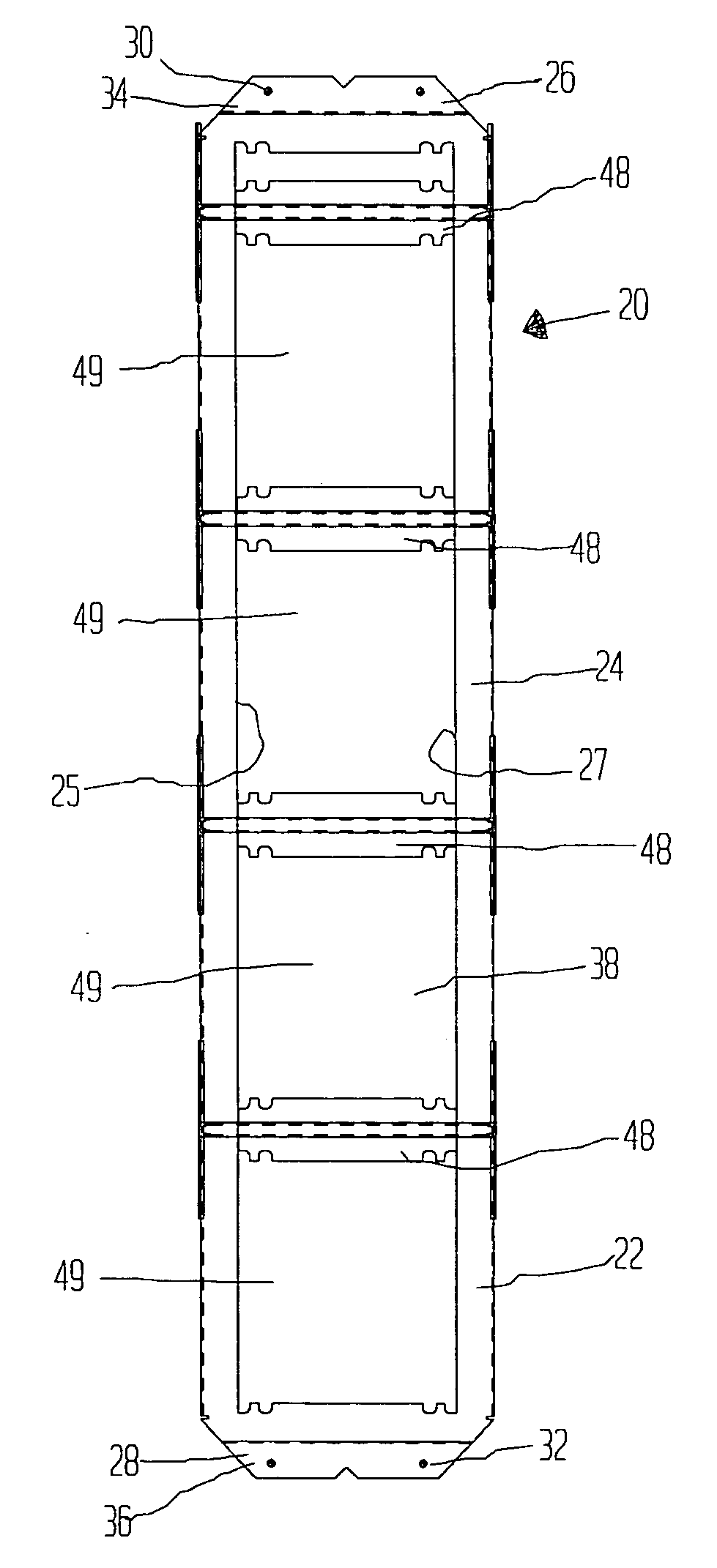
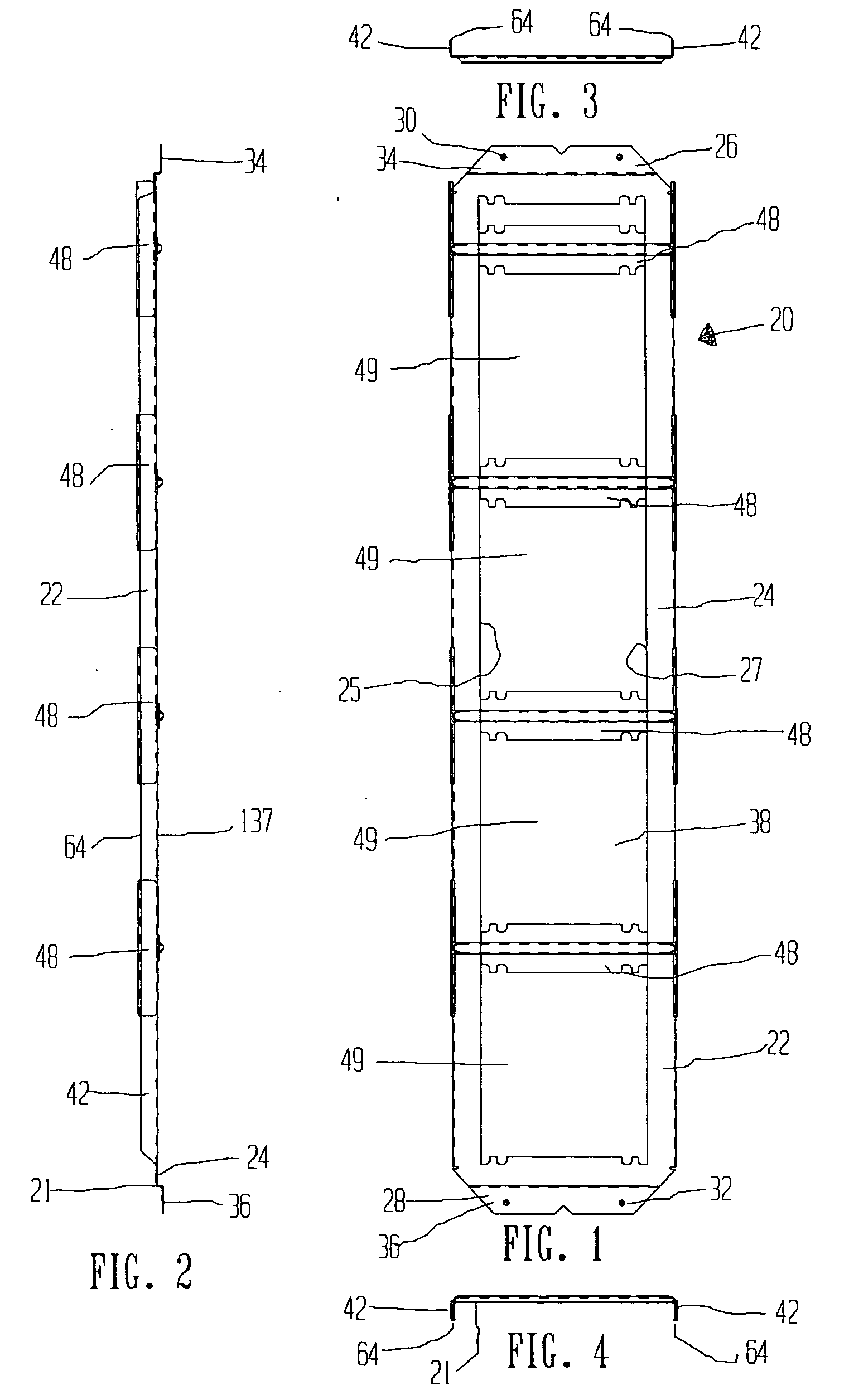
[0046] In general, the present invention is directed to improved brackets for use in mounting electrical boxes to structural members in walls, floors and ceiling, such as studs in walls of buildings or joists in floors or ceilings. Referring to FIGS. 1-4, the present invention will be described. The embodiment of FIGS. 1-4 is directed to a bracket that is made from a single unitary piece of flat stock, in the alternative the mounting bracket may be made from component parts that are assembled into a finished, or completed mounting bracket. As is well known, a conventional, type bracket is manufactured from a single piece of material, such as metal and as described in the '137 patent. The mounting bracket of FIGS. 1-27 includes novel features that provide additional functionality and that are significant improvements over the mounting brackets described in the '137 patent and elsewhere in the prior art. With reference to FIGS. 1-27, like numbers describe like parts.

[0047] Referring t...

second embodiment

[0057] However, as will be described in greater detail, the sliding rail portion 140 of the bracket 21 may be made in separate pieces 140A, 140B and 140C and is constructed so as to have a sliding or telescoping relationship with integrally formed track section 144 of bracket 21. As shown, for example, in FIGS. 14-16, the pair of rails 140A, 140B are fashioned to slide within the pair of tracks 144A, 144B so that varying distances between structural members, such as wall studs, may be accommodated. As shown in FIG. 14, this second embodiment of the present invention provides for installation of up to three connection boxes.

[0058] Shown in FIG. 16 is an end view of the rail sections 140A and 140B, with a folded over portion having preferably a substantially triangular cross-section of small enough area such that the rail sections 140A, 140B slide within the tracks 144A, 144B of track section 144, which have a substantially triangular cross-section sized and shaped to accept rail sect...


PUM


Abstract

Electrical box mounting bracket for use in mounting electrical connection boxes between structural members in walls, floors or ceilings, such as, for example, between wall studs, ceiling joists or floor joists, separated by predetermined distances, such as 16 inches, 24 inches, or other distances, having mounting screw hole locations and orientations designed to permit mounting of standard 4 inch and 4 11/16 inch electrical connection boxes to the bracket at any location between the two ends of the bracket and which provides for closure of the gap or additional unused opening area which typically exists between the box cover and the two sidewall edges of the connection box that span the width of the bracket frame. The sides of the bracket may be of fixed length or have a sliding relationship so that the length of the bracket from end to end may be adjusted. Further an electrical connection box and bracket are provided that allows the electrical connection box to be initially attached to the bracket without the use of screws or other separate fasteners, to facilitate the installation—or “pulling”—of electrical wiring. It is emphasized that this abstract is provided to comply with the rules requiring an abstract that will allow a searcher or other reader to quickly ascertain the subject matter of the technical disclosure. It is submitted with the understanding that it will not be used to interpret or limit the scope of the claims.

Description

CROSS REFERENCE TO RELATED APPLICATIONS [0001] This application claims the benefit of U.S. Provisional Application Ser. No. 60 / 533,499 filed Dec. 31, 2003, which is incorporated herein by reference.BACKGROUND OF THE INVENTION [0002] A. Field of the Invention [0003] The present invention is directed to mounting brackets used for mounting or supporting electrical connection boxes. [0004] B. Description of the Prior Art [0005] Various types of brackets used for mounting or supporting electrical connection boxes are known. For example, U.S. Pat. No. 5,330,137 (the '137 patent) to Oliva describes apparatus and method for mounting an electrical box between studs in a wall. Embodiments of the present invention include improvements to the mounting brackets as described in the '137 patent, which is incorporated by reference herein. The mounting bracket of the '137 patent is of a unitary construction, having an open face, and is of a length of either 16 or 24 inches, to accommodate the distan...

Claims


Application Information

Patent Timeline
IPC IPC(8): H01R4/66H02G3/08H02G3/12
CPCH02G3/125H02G3/086
Inventor CHEATHAM, JAMES F.MILNE, FRED
Owner CHEATHAM JAMES F
Why Eureka
Try Eureka