Structure of transmission for bicycle

Inactive Publication Date: 2005-08-11
HONDA MOTOR CO LTD
View PDF10 Cites 28 Cited by
  • Summary
  • Abstract
  • Description
  • Claims
  • Application Information

AI Technical Summary

Benefits of technology

[0008] It is an object of the present invention to solve such a problem, and to provide an improved structure of the derailleur shaft moun

Problems solved by technology

According to the cantilever supporting structure of the derailleur (shifting frame) as disclosed in the above document, sufficient rigidity of the derailleur shaft (movable member) is

Method used


Image

  • Structure of transmission for bicycle
  • Structure of transmission for bicycle
  • Structure of transmission for bicycle

Examples


Example

[0038] Referring now to FIGS. 1 to 18, embodiments of a structure of a transmission for a bicycle provided with a derailleur according to the present invention will be described.

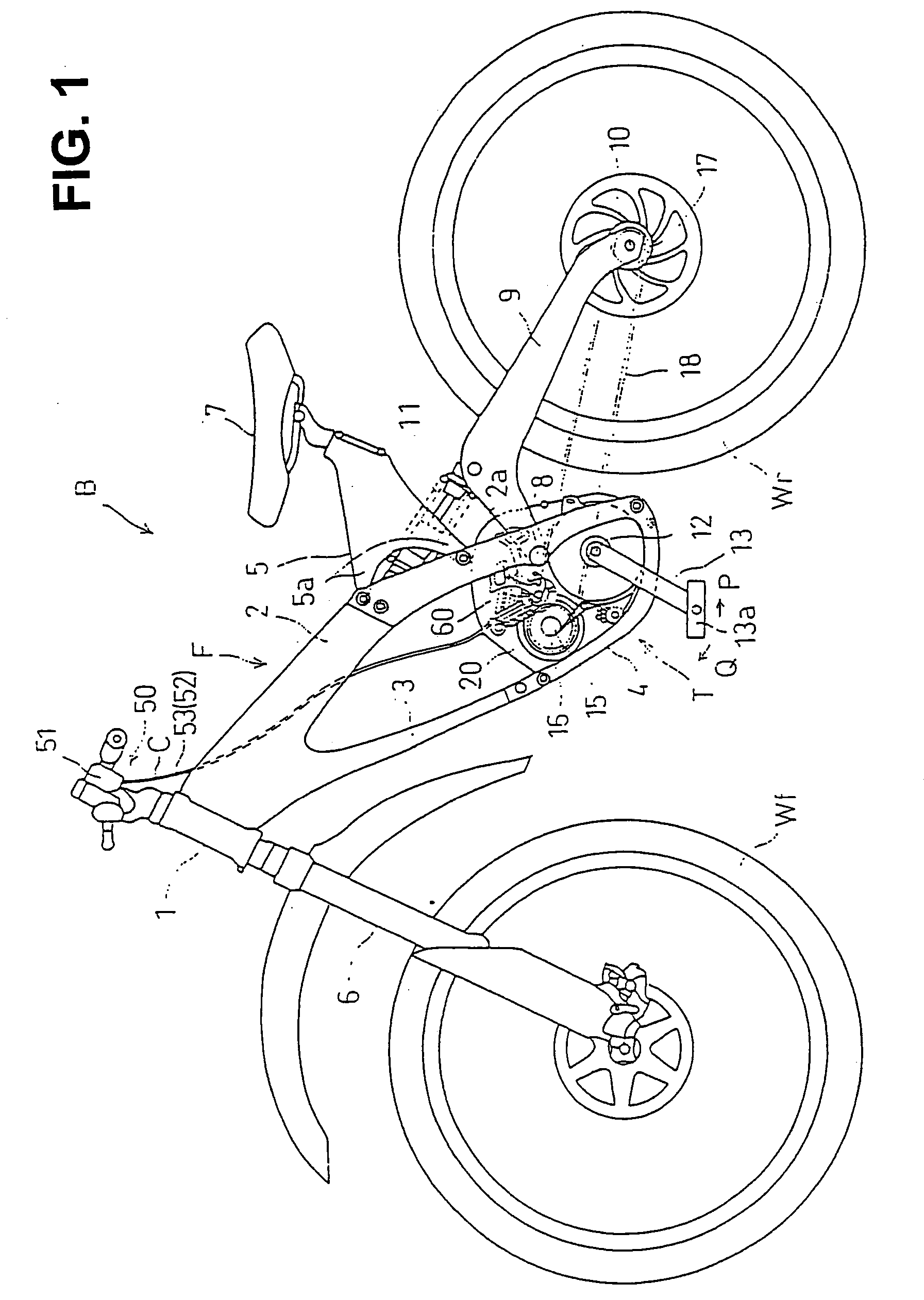
[0039]FIG. 1 is a left side view of a bicycle B in which a transmission T having a derailleur is used according to the present invention.

[0040] The bicycle B is a downhill bicycle, and is used, for example, for competitive sports that are timed for running down a dirt course, such as a forest road provided with a high-speed corner or a jumping section.

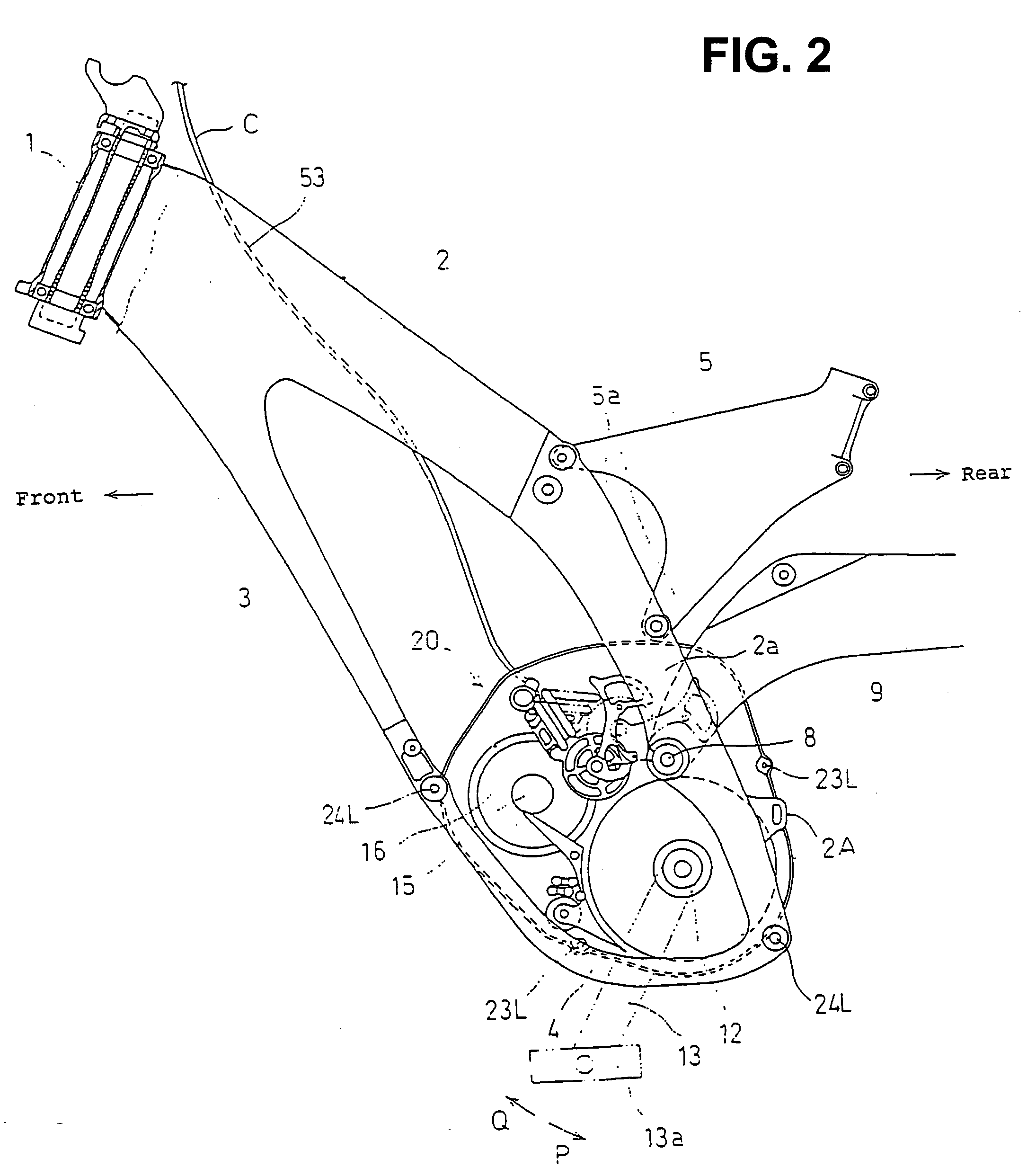
[0041] A vehicle body frame F of the bicycle B includes, as shown in FIGS. 1 and 2, a pair of left and right mainframes 2 extending from a head pipe 1 rearward and obliquely downward. A down tube 3 extends from the front lower ends of both mainframes 2 rearward and obliquely downward. The lower ends of a pair of the mainframes 2 and the lower end of the down tube 3 are connected to each other via an under tube 4. A saddle frame 5 is provided so as to extend ...


PUM


Abstract

To achieve downsizing and weight reduction of a derailleur shaft and the mounting structure thereof and to improve the rigidity of the derailleur shaft without increasing the thickness thereof more than necessary. A transmission case is divided into left and right halves, and the left and right halves are provided with bosses therein having holes opposing each other. The bosses are brought into abutment with each other and united by fitting tightening bolts to the holes of the bosses and tightening the same. A sleeve-shaped derailleur shaft is fitted on the outer periphery of the bosses to support and mount the derailleur shaft. The derailleur shaft includes a hole at the shaft end thereof. A mounting position of the derailleur shaft is achieved by a pin inserted into the hole and a hole provided on one of the cases.

Description

CROSS-REFERENCE TO RELATED APPLICATIONS [0001] This non-provisional application claims priority under 35 U.S.C. § 119(a) on Patent Application No. 2004-068101, filed in Japan on Feb. 10, 2004, the entirety of which is incorporated herein by reference. BACKGROUND OF THE INVENTION [0002] 1. Field of the Invention [0003] The present invention relates to a structure of a transmission for a bicycle including a derailleur. In particular, the present invention relates to an improved structure of a transmission for a bicycle characterized by the mounting structure of the derailleur in the transmission. [0004] 2. Description of Related Art [0005] In the related art, a transmission for a bicycle provided with a derailleur is known. The derailleur has a supporting arm with a pantograph mechanism, which is adapted to shift a power transmission chain wound around a multi-stage sprocket wheel supported by a rear wheel hub and mounted to the rear wheel hub via a shaft step-by-step is known. The de...

Claims


Application Information

Patent Timeline
IPC IPC(8): B62M9/121B62M9/124B62M9/1242B62J13/00B62M9/125B62M9/128B62M9/131B62M11/14F16H57/021
CPCB62M11/145B62M9/121
Inventor MATSUMOTO, SHINYAIGUCHI, KAZUNARI
Owner HONDA MOTOR CO LTD
Why Eureka
Try Eureka