
Electro-optic liquid level sensing system for aircraft beverage brewing

Active Publication Date: 2005-08-18
BE INTPROP
View PDF6 Cites 24 Cited by
  • Summary
  • Abstract
  • Description
  • Claims
  • Application Information

AI Technical Summary

Benefits of technology

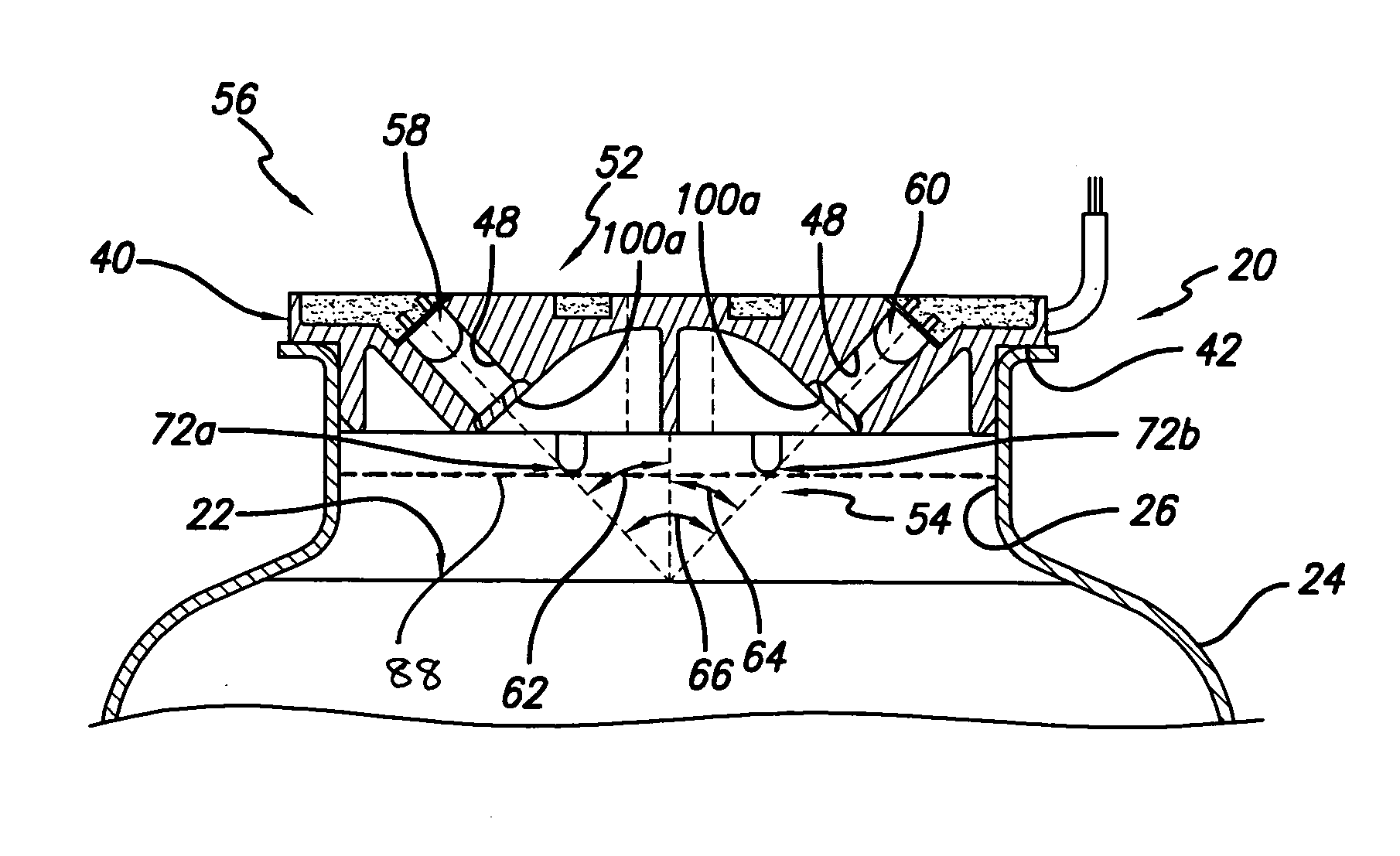
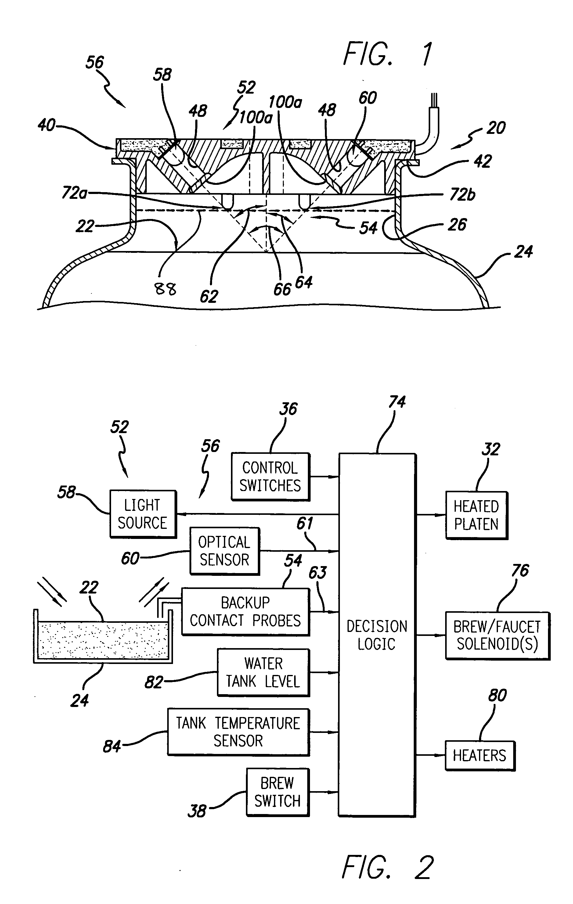
[0009] In one presently preferred embodiment, the apparatus includes a support housing adapted to mate with the upper opening of the container, primary liquid level sensing means mounted in the support housing for non-intrusively measuring the level of the surface of the liquid in the container; and secondary liquid level sensing means mounted in the support housing for intrusively sensing a predetermined level of the surface of the liquid in the container for preventing accidental overflows in the event of a malfunction of the primary liquid level sensing means.
[0018] In another preferred embodiment, the invention provides for an apparatus for detecting a level of a surface of a liquid in a container having an upper opening, including a support housing adapted to mate with the upper opening of the container, and at least one primary retractable liquid level sensing probe pivotally mounted in the support housing for measuring the level of the surface of the liquid in the container. The apparatus may also further include a secondary liquid level sensing probe fixedly mounted in the support housing for sensing a predetermined level of the surface of the liquid in the container for preventing accidental overflows in the event of a malfunction of the primary liquid level sensing means.
[0019] The present invention also provides for a method for detecting a level of a surface of a liquid in a container having an upper opening, such as for a server container of a beverage maker for a transport system, such as for aircraft, trains, trucks, buses and the like. A support housing is provided that is adapted to mate with the upper opening of the container, and a primary liquid level sensing means is mounted in the support housing for non-intrusively measuring the level of the surface of the liquid in the container. In one aspect, the primary liquid level sensing means may be an optical sensor device mounted in the support housing for non-intrusively measuring the level of the surface of the liquid in the container, the optical sensor device including a light emitting device, such as an infrared light emitting device, for projecting incident light on the surface of the liquid in the container, and a light detecting device, such as a phototransistor, for detecting the incident light reflected from the surface of the liquid in the container. The light source is typically driven continuously during a brew cycle, but the method of the invention provides for pulsing power to the light emitting device, allowing the system to turn the light emitting device on for only a fraction of the time during which the beverage maker is in operation, thus increasing the useful life of the light emitting device, and / or reducing the power requirements. Although the light detecting device typically continuously measures reflected emitted light, the method of the invention similarly provides for monitoring the light detecting device only when the light emitting device is on, so that the liquid level can be detected at various intervals.
[0020] The provision of protective lenses significantly improves protection of non-intrusive primary liquid level sensors such as light emitting and light receiving devices from direct water condensation. In addition, water condensation forming on and above the lenses will run off the outer surfaces of the protective lenses, so that the lenses tend to be cleaned from coffee residue during each brew cycle, requiring no special cleaning of the lenses. Since the lenses are hermetically sealed or integrally formed on the support housing housing, no coffee residue can build up between the non-intrusive primary liquid level sensors and the support housing housing. Therefore the optical system of the invention avoids creation of “dirt traps” which are unacceptable on food processing equipment.
[0021] The secondary intrusive backup liquid level sensing probes also advantageously serve to prevent accidental overflows in case of a malfunction of the primary non-intrusive liquid level sensing device. The backup probes provide a high reliability system for preventing accidental overflow, and operate in conjunction with primary non-intrusive liquid level sensing system, so that if one of the liquid level sensing systems fails, the other will stop the brew cycle before the server overflows.

Problems solved by technology

When such techniques are used for measuring liquid level in a server container of a beverage brewing apparatus, such as a coffee brewing machine, these techniques require a sensing device to extend into the server container to contact the liquid, which subjects the sensing device to damage when the server container is repetitively installed and removed from the beverage maker brewing cavity.
A temperature sensor included with the liquid level sensor that extends intrusively to contact the liquid is also vulnerable to being damaged by repeated usage.
Another inherent problem with this approach is that the light emitting and sensing optical sensors are not protected from the steam, water condensation and accumulation of coffee residue, and frequent cleaning operations are required to keep the level sensing system operational, which is time consuming and expensive.
Failure to perform these cleaning operations typically results in uncontrolled overflows due to accumulation of debris and coffee residue on the light emitting and sensing optical sensors.
Such conventional liquid level sensing systems also typically do not provide any redundancies in the event that the primary sensing apparatus monitoring the liquid level fails, either by internal failure or due to coffee residue build up.
Failure to detect the liquid level will result in an overflow, which is not only inconvenient, but also dangerous for the operator.
During an overflow, very hot liquid typically comes out of the server and the beverage maker, and spills out, potentially burning the operator attending the machine.

Method used


Image

  • Electro-optic liquid level sensing system for aircraft beverage brewing
  • Electro-optic liquid level sensing system for aircraft beverage brewing
  • Electro-optic liquid level sensing system for aircraft beverage brewing

Examples


Embodiment Construction

[0041] The present invention provides for an apparatus for detecting a level of a surface of a liquid in a container having an upper opening, such as for a server container of a beverage maker for a transport system, such as for aircraft, trains, trucks, buses and the like.

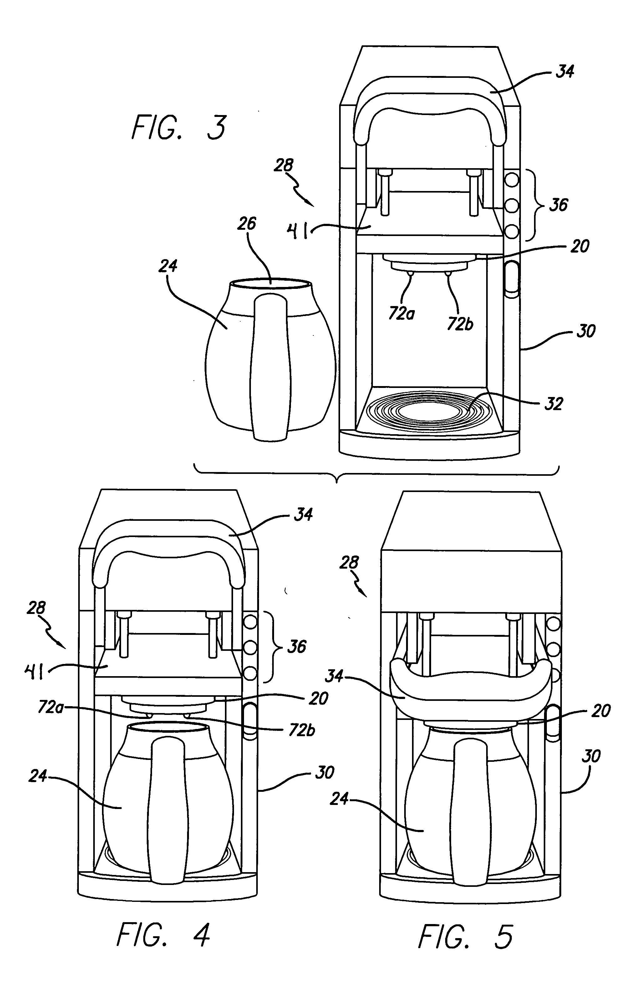
[0042] In a first embodiment illustrated in FIGS. 1-9, the present invention accordingly provides for an apparatus 20 for detecting a level of a surface of a liquid 22 in a container 24 typically having an upper opening 26 such as a server container of a beverage maker such as a coffee brewer 28 for a transport system (not shown), such as for aircraft, trains, trucks, buses and the like. The beverage maker typically includes an enclosure 30 including a heated platen or hot plate 32 on which the server container is seated in the beverage maker, and a brew handle lever 34 movable between an “up” or “unlocked” position in which the server container may be freely moved into and out of the beverage maker, and a “down”...


PUM


Abstract

The electro-optic liquid level sensing system detects a level of liquid in a container having an upper opening, such as for a server container of a beverage maker for a transport system, such as for aircraft, trains, trucks, buses and the like. A support housing mates with the upper opening of the container, and a primary liquid level sensor is mounted in the support housing for non-intrusively measuring the liquid level. A secondary liquid level sensor may be mounted in the support housing to sense a predetermined liquid level to prevent accidental overflows. Protective lenses may be placed in front of the primary liquid level sensor.

Description

BACKGROUND OF THE INVENTION [0001] 1. Field of the Invention [0002] This invention relates to liquid level detection systems, and more particularly, to a system to detect the liquid level in a server container of a beverage brewing apparatus adapted for use on aircraft. [0003] 2. General Background and State of the Art [0004] One conventional technique for determining the level of a liquid in a vessel or container involves mechanically measuring the liquid level with a contact device such as a float indicator, dip stick or probe which extends intrusively into the liquid to be measured. When such techniques are used for measuring liquid level in a server container of a beverage brewing apparatus, such as a coffee brewing machine, these techniques require a sensing device to extend into the server container to contact the liquid, which subjects the sensing device to damage when the server container is repetitively installed and removed from the beverage maker brewing cavity. [0005] On...

Claims


Application Information

Patent Timeline
IPC IPC(8): A47J31/44G01F23/00G01F23/24G01F23/292G01F23/296
CPCA47J31/44A47J2203/00G01F23/241G01F25/0061G01F23/292G01F23/2928G01F23/296G01F23/242A47J31/005G01F25/20
Inventor RAMUS, SEBASTIEN A.DEBALD, KEITH R.DETTMER, JOSEPH C.FLIESS, WINSTON S.
Owner BE INTPROP
Learn More