Engine fuel injection control system

a fuel injection control and engine technology, applied in the direction of electrical control, process and machine control, instruments, etc., can solve the problems of decrease of fuel injection amount, and inability of injection methods to perform appropriate transfer between injection methods responsive to the amount, so as to suppress deterioration, improve suction efficiency, and suppress deterioration of combustion state

Inactive Publication Date: 2005-08-18
TOYOTA JIDOSHA KK
View PDF8 Cites 143 Cited by
  • Summary
  • Abstract
  • Description
  • Claims
  • Application Information

AI Technical Summary

Benefits of technology

[0008] In order to solve the problems described above, an object of the invention is to suppress deterioration in the combustion states by adjusting an appropriate fuel injection method to comply with the combustion state even when the circumstances would not permit normal fuel injection from cylinder injector due to causes such as deposit accumulation, as well as ensuring the effect of suction efficiency improvement by cylinder injection to a maximum extent.
[0009] In order to achieve the above objective, the present invention provides a system for controlling fuel injection in a combustion engine. The combustion engine has a cylinder and an intake passage connected to the cylinder. A first injector injects fuel into the cylinder. A second injector injects fuel into the intake passage. The fuel injection by the first injector and the second injector is controlled based on a respectively predetermined injection ratio. The system comprises a sensor for sensing an actual amount of fuel injected from said first injector. The system further comprises a controller for determining a deviation of the actual injection amount from a predetermined target injection amount, correcting at least one of said injection ratios based on the deviation, and actuating said second injector to perform fuel injection together with the first injector.
[0010] In one aspect, the injection ratio of the intake passage injector is increased based on the detection that the amount of fuel injected is liable to be lower than the target injection amount.
[0011] In this structure, the difference between the target injection amount and the amount of fuel actually injected from the cylinder injector 17 is detected. Th...

Problems solved by technology

The accumulation of the deposits can decrease the amount of fuel injected and can change the injection conditions after time so that the combustion state can be deteriorated.
However, the periodic transfer between the injection methods cannot perform appropriate transfer between the injection methods responsive to the amount of the accumulated deposits because the changeover can take place even when the deposits have not yet actually accumulated.
Further, because the cylinder injection is discontinued when totally s...

Method used


Image

  • Engine fuel injection control system
  • Engine fuel injection control system
  • Engine fuel injection control system

Examples


Embodiment Construction

[0028] An embodiment of the invention is described below by referring to FIGS. 1 to 4.

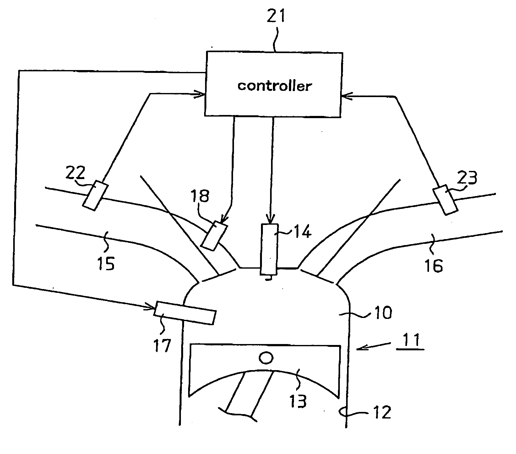
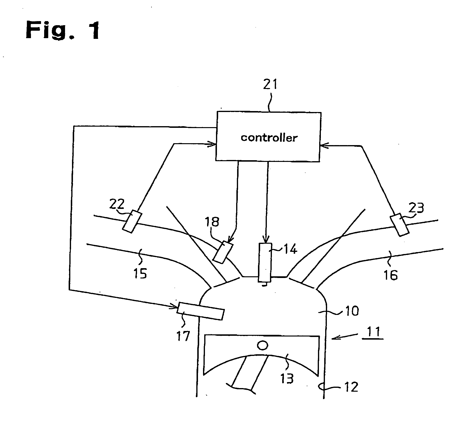
[0029]FIG. 1 schematically shows a system for controlling fuel injection of the engine in an embodiment according to the invention. A piston 13 is disposed within the cylinder 12 of the engine 11. The intake passage 15 and an exhaust passage 16 are respectively connected to the combustion chamber 10 defined by the piston 13.

[0030] The intake passage injector 18 is provided on the intake passage 15 for injecting fuel into the intake passage 15. The cylinder injector17 is provided on the cylinder 12 in a manner in which the tip of the injector is exposed within the combustion chamber 10 so that fuel can be directly injected from the orifice (not shown in the figures) of the cylinder injector 17 into the combustion chamber 10. The fuel thus injected from the intake passage injector 18 or the cylinder injector 17 are mixed with the suction air introduced into the combustion chamber 10 through the int...


PUM


Abstract

A system for controlling fuel injection in an engine. The engine includes an intake passage, an intake passage injector, a cylinder having a combustion chamber, and a cylinder injector for injecting a target amount of fuel into the combustion chamber. The system includes a controller for controlling the intake passage and cylinder injectors to permit fuel injection, each with an injection ratio, while said engine operates in a condition in which said engine permits fuel injection from said cylinder injector, a sensor for sensing the amount of fuel injected from the cylinder injector, a detector for detecting the difference between the target injection amount and the amount of fuel injected and an adjustor for adjusting the injection ratio based on the result of the detection by the detector so that the intake passage injector performs fuel injection together with the fuel injection performed by the cylinder injector.

Description

BACKGROUND OF THE INVENTION [0001] The present invention relates to a system for controlling fuel injection in an internal combustion engine that has a cylinder injector for directly injecting fuel into a combustion chamber defined inside a cylinder, and a port injector for injecting fuel into an air-intake passage. [0002] Conventionally, fuel injection into the intake passage, such as an intake port (hereinafter referred to as “port injection”), has been widely used for supplying fuel into the combustion chamber. In the port injection, the fuel is injected into a passage upstream of the intake valve that is disposed at the entrance of the cylinder. The fuel injected in this manner is introduced into the combustion chamber during the suction stroke of the cylinder in a mixed state substantially uniformly with the air. [0003] On the other hand as an alternative injection method, direct injection of the fuel into the cylinder (hereinafter referred to as “cylinder injection”) has recen...

Claims


Application Information

Patent Timeline
IPC IPC(8): F02B17/00F02D45/00F02B23/10F02B75/12F02D41/04F02D41/14F02D41/24F02D41/30F02D41/34F02D41/40
CPCF02B23/104F02B2075/125F02B2275/16F02D41/047F02D41/2454F02D41/2461Y02T10/123F02D41/248F02D41/2493F02D41/3094F02D41/40Y02T10/125Y02T10/44F02D41/2467Y02T10/12Y02T10/40
Inventor SATOU, FUMIKAZU
Owner TOYOTA JIDOSHA KK
Why Eureka
Try Eureka