Automotive air conditioning system

a technology for air conditioning systems and automobiles, applied in the direction of domestic cooling devices, lighting and heating devices, nuclear elements, etc., can solve the problem of insufficient heating effect of the interior of the passenger compartment, and achieve the effect of increasing the immediate effect of heating performan

Inactive Publication Date: 2005-08-18
DENSO CORP
View PDF10 Cites 105 Cited by
  • Summary
  • Abstract
  • Description
  • Claims
  • Application Information

AI Technical Summary

Benefits of technology

[0009] The present invention was made in view of the aforesaid situations, and an object thereof is to increase the immediate effect of the heating performance in the passenger compartment.

Problems solved by technology

In the related art, while the amount of water that is to be heated by the electric heater is limited, since the specific heat of water is very high, it takes time to heat water to a predetermined temperature by means of the electric heater, and the immediate effectiveness in heating the interior of the passenger compartment is insufficient.

Method used


Image

  • Automotive air conditioning system
  • Automotive air conditioning system
  • Automotive air conditioning system

Examples


first embodiment

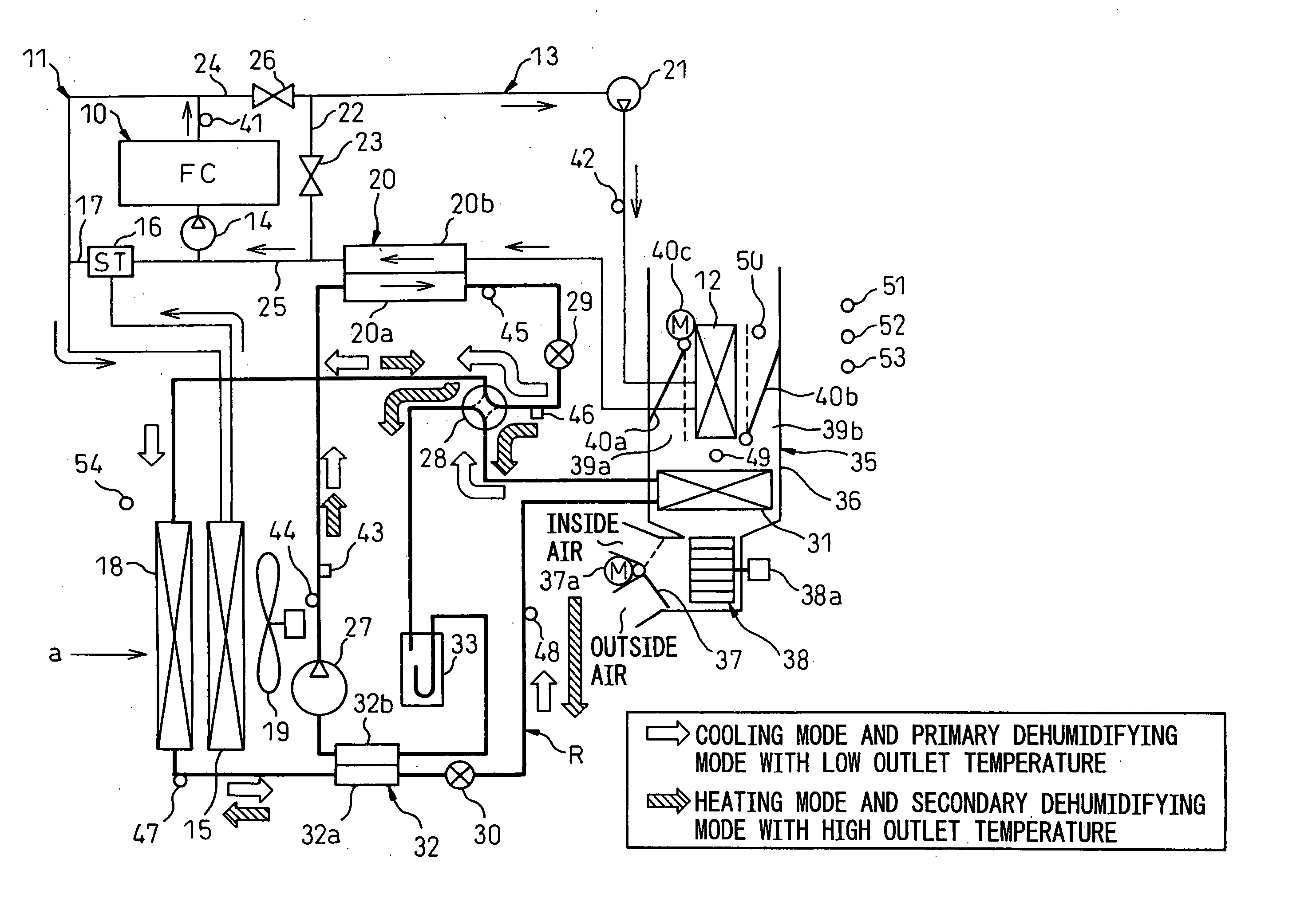
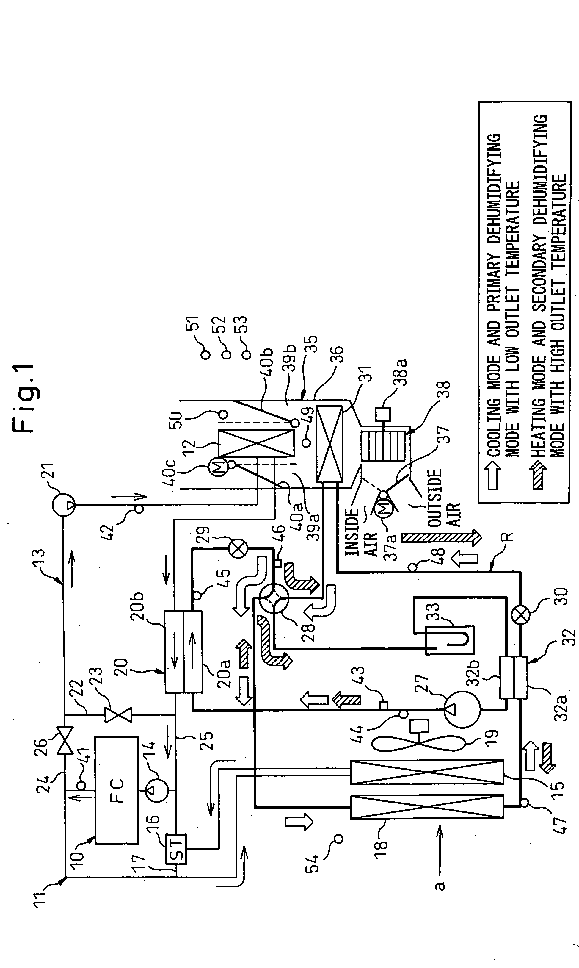
[0058]FIG. 1 is an overall system configuration diagram including a refrigeration cycle R, a hot water circuit and an inner air conditioning unit portion. In this embodiment, an example is illustrated in which an apparatus according to the invention is applied to a fuel cell installed vehicle having a fuel cell (FC stack). 10 which generates electric power that is supplied to an automotive driving motor (not shown).

[0059] As is generally known, the fuel cell 10 is such as to function to generate electric power through a chemical reaction between oxygen and hydrogen, and when the fuel cell 10 generates electric power, heat is generated together with electric energy. In order to generate electric power efficiently using the fuel cell 10, the fuel cell 10 needs to be cooled so as to be maintained in an appropriate temperature range (for example, on the order of 60 to 80°). To make this happen, in this embodiment, the fuel cell 10 is provided along a hot water (coolant) circuit through...

second embodiment

[0143] While, in the first embodiment, the example of controlling the hot water circuit has been described with an emphasis being put on the importance of the increase in immediate effectiveness in heating in the initial stage of starting up the fuel cell 10, in a second embodiment, warming up of the fuel cell 10 when the temperature is low is attempted to be promoted.

[0144]FIG. 5 shows a flowchart illustrating an example of controlling the hot water circuit according to the second embodiment, and a determination step is added to that shown in FIG. 4 in which the coolant temperature TW1 on the fuel cell 10 side (the temperature detected by the sensor 41) is determined in step S360. In this determination step S360, whether or not the coolant temperature TW1 on the fuel cell 10 side is equal to or lower than a predetermined low temperature b (for example, 0° C.) which requires warming up to be promoted is determined. Then, if the coolant temperature TW1 on the fuel cell 10 side is eq...

third embodiment

[0147] While, in the first embodiment, the coolant-refrigerant heat exchanger 20 in the refrigeration cycle R is connected to the downstream side of the hot water type heater core 12 in the secondary hot water circuit 13, in a third embodiment, as shown in FIG. 6, the coolant-refrigerant heat exchanger 20 in the refrigeration cycle R is connected to the upstream side of the hot water type heater core 12 in the secondary hot water circuit 13.

[0148] By adopting this construction, in the third embodiment, hot water heated by the coolant-refrigerant heat exchanger 20 is allowed to flow into the hot water type heater core 12 immediately. Due to this, the heat of high temperature hot water that has been heated in the coolant-refrigerant heat exchanger 20 can be used effectively to heat the interior of the passenger compartment without being dissipated at other locations in a wasteful fashion. As a result, the rise in the heating of the passenger compartment can be promoted further. Note ...


PUM


Abstract

An automotive air conditioning system has a primary hot water circuit 11 located on a side where a vehicle installed heat generator 10 is located and a secondary hot water circuit 13 which includes a hot water type heater core 12 for heating passenger compartment outlet air, whereby when in a heating mode, in the event that a coolant temperature TW1 of the primary hot water circuit is lower than a coolant temperature TW2 of the secondary hot water circuit 13, an opening and closing valve 26 is closed, whereas an opening and closing valve 23 is opened, so that a state is created in which the hot water circuits 11, 13 are separated from each other. On the other hand, in the event that the coolant temperature TW1 of the primary hot water circuit becomes higher than the coolant temperature TW2 of the secondary hot water circuit 13, the opening and closing valve 26 is opened, whereas the opening and closing valve 23 is closed, so that a state is created in which the hot water circuits 11, 13 are connected to each other.

Description

BACKGROUND OF THE INVENTION [0001] 1. Field of the Invention [0002] The present invention relates to an automotive air conditioning system having a hot water type heater core for heating air using hot water as a heat source and a coolant-refrigerant heat exchanger for heating hot water using a refrigerant discharged from a compressor in a refrigeration cycle as a heat source, and more specifically to an automotive air conditioning system which is effective when applied to vehicles having a fuel cell installed therein, electric vehicles or hybrid vehicles in which less waste heat is generated from the engine installed therein. [0003] 2. Description of the Related Art [0004] Japanese Unexamined Patent Publication No. 11-208250 discloses a hot water circuit configuration for a conventional automotive air conditioning system having a hot water type heater core for heating air using hot water (coolant) from an engine installed in a vehicle as a heat source, which hot water circuit config...

Claims


Application Information

Patent Timeline
Patent Type & Authority Applications(United States)
IPC IPC(8): B60H1/00B60H1/08B60H1/22B60H3/00B61D27/00G21C9/00
CPCB60H1/00385Y02T10/70B60H2001/00307B60H2001/00928B60H2001/00957B60L1/003B60L1/02B60L11/14B60L11/1885B60L11/1892B60L11/1894B60L2240/34B60L2240/36Y02T10/7077Y02T90/34B60H1/00907B60L50/16B60L58/31B60L58/33B60L58/34Y02T10/7072Y02T90/40
Inventor ITOH, SATOSHITOMATSU, YOSHITAKAKURODA, YASUTAKA
Owner DENSO CORP
Why Eureka
Try Eureka