Optical waveguide displacement sensor

a technology of optical waveguide and displacement sensor, which is applied in the field of displacement sensors, can solve the problems of limited ability to interrogate an unknown molecule, bulky, expensive or slow, and limited information ability of these techniques,

Inactive Publication Date: 2005-08-18
CORNELL RES FOUNDATION INC
View PDF32 Cites 97 Cited by
  • Summary
  • Abstract
  • Description
  • Claims
  • Application Information

AI Technical Summary

Benefits of technology

[0010] The cantilever resonators in one embodiment are a resonance-frequency-based biological mass sensor, comprised of a low-stress silicon nitride (bulk micromachined) as well as stress free poly-silicon (surface micromachined) cantilever beams. The cantilever beams are integrated with optical deflection, for the detection of molecules. In one embodiment, single Escherichia coli O157:H7 (E. coli)-cell-antibody binding events as well as selectively bound self assembled monolayers (SAMs) are detected.

Problems solved by technology

These methods suffer from various disadvantages relating to their use as sensitive mass sensors due to complex mounting requirements, lack of sensitivity, difficult fabrication, and environmental instability.
Most current detection technologies are either, bulky, expensive or slow.
Current instrumentation for single molecule detection is largely based upon direct optical measurements which provide a limited ability to interrogate an unknown molecule.
The ability of these techniques to be informative is limited and this is especially true of molecules with a limited unique optical spectra and where there are a number of molecules in the milieu with similar spectral signatures.
Also, these techniques require expensive accessories, as single wavelength lasers are required and are tuned to the fabricated device.

Method used


Image

  • Optical waveguide displacement sensor
  • Optical waveguide displacement sensor
  • Optical waveguide displacement sensor

Examples


Embodiment Construction

[0018] In the following description, reference is made to the accompanying drawings that form a part hereof, and in which is shown by way of illustration specific embodiments in which the invention may be practiced. These embodiments are described in sufficient detail to enable those skilled in the art to practice the invention, and it is to be understood that other embodiments may be utilized and that structural, logical and electrical changes may be made without departing from the scope of the present invention. The following description is, therefore, not to be taken in a limited sense, and the scope of the present invention is defined by the appended claims.

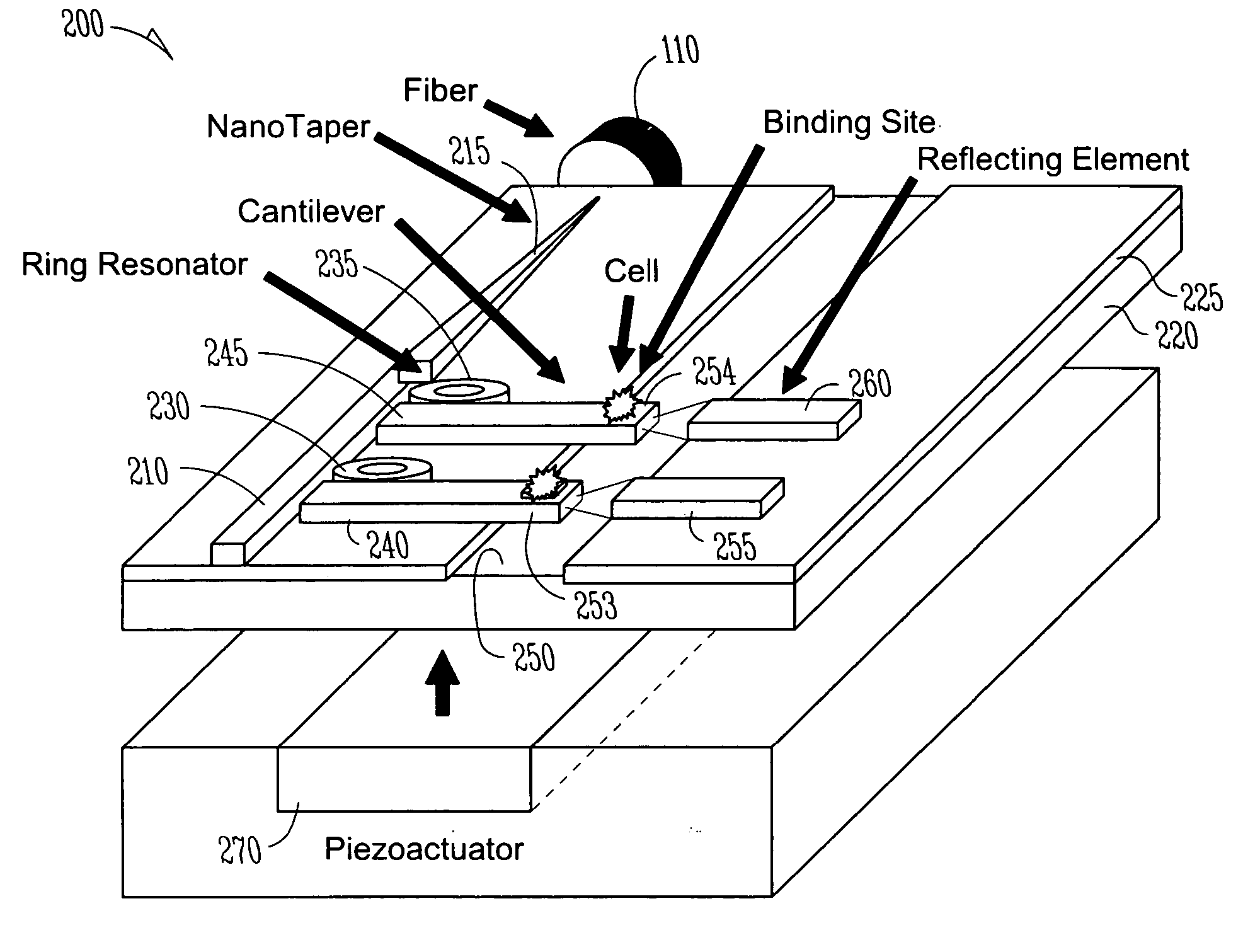
[0019] A block diagram schematic of an analytical chip 100 is shown in FIG. 1. Light, represented by arrow 105 is provided by an optical fiber 110. The light 105 is provided via a coupler 113 to a silicon waveguide 115, that is supported by a substrate 120 and layer of oxide 125 formed on top of the substrate. The waveguide ...


PUM


Abstract

A substrate incorporates a mechanical cantilever resonator with passive integrated optics for motion detection. The resonator acts as a waveguide, and enables optical detection of deflection/displacement amplitude, including oscillations. In one embodiment, the cantilever comprises a silicon waveguide suspended over a substrate. A reflector structure faces a free end of the suspending cantilever, or a waveguide is supported facing the free end of the suspended cantilever to receive light transmitted through the silicon waveguide cantilever. Deflection/displacement of the cantilever results in modulation of the light received from its free end that is representative of the displacement. Ring resonators may be used to couple different wavelength light to the waveguides, allowing formation of an array of cantilevers.

Description

FIELD OF THE INVENTION [0001] The present invention relates to displacement sensors, and in particular to an optical waveguide displacement sensor. BACKGROUND OF THE INVENTION [0002] Cantilever beams micro-machined in silicon are currently used as displacement sensors in such devices as atomic force microscopes, magnetic force microscopes and other force based scanning probe techniques where force applied to the cantilever causes a physical displacement that is detected. Cantilever beams are also used to sense vibrations of structures, inertial force, and to detect mass of the cantilever itself. [0003] Cantilever displacement or deflection has been detected by several different methods. The methods include deflection of an external laser beam reflecting off of the cantilever, piezoresistive measurements, capacitance change between cantilever and substrate, and measurement of tunneling current. These methods suffer from various disadvantages relating to their use as sensitive mass se...

Claims


Application Information

Patent Timeline
Patent Type & Authority Applications(United States)
IPC IPC(8): G01D5/26G02B6/00G02B6/30G02B6/35
CPCG01D5/266G01D5/268G02B6/3578G02B6/3502G02B6/3566G02B6/305
Inventor PANEPUCCI, ROBERTO R.ILIC, BOJANLIPSON, MICHALALMEIDA, VILSON ROSA DE
Owner CORNELL RES FOUNDATION INC
Why Eureka
Try Eureka