Micro lens array and a method of manufacturing a replication mold for the same

Active Publication Date: 2005-08-18
JVC KENWOOD CORP A CORP OF JAPAN
View PDF2 Cites 25 Cited by
  • Summary
  • Abstract
  • Description
  • Claims
  • Application Information

AI Technical Summary

Benefits of technology

[0036] According to the method of manufacturing a replication mold for a micro lens array of the fourth aspect, since blast-grinding and etching are co-employed to closely form a plural of concave portions on the upper surface of the substrate and to form a plural of hollows for sub-lenses along the inner surface of each concave portion for a micro lens, the replication mold for manufacturing a micro lens array in which a plural of sub-lenses are protrusively formed on the surface of each micro lens is obtained conveniently and less costly. Moreover, since blast-grinding and etching are co-employed, the replication mold for a micro lens array is obtained at shorter times.
[0037] Moreover, according to the m

Problems solved by technology

The above-mentioned direct-view-type display is somewhat disadvantageous in that image quality changes with observation angles.
At worst, the display is unobservable when seen from a certain view angle or above.
That is, this type of display has a disadvantage in that an appropriate angle of vi

Method used


Image

  • Micro lens array and a method of manufacturing a replication mold for the same
  • Micro lens array and a method of manufacturing a replication mold for the same
  • Micro lens array and a method of manufacturing a replication mold for the same

Examples


first embodiment

A First Embodiment

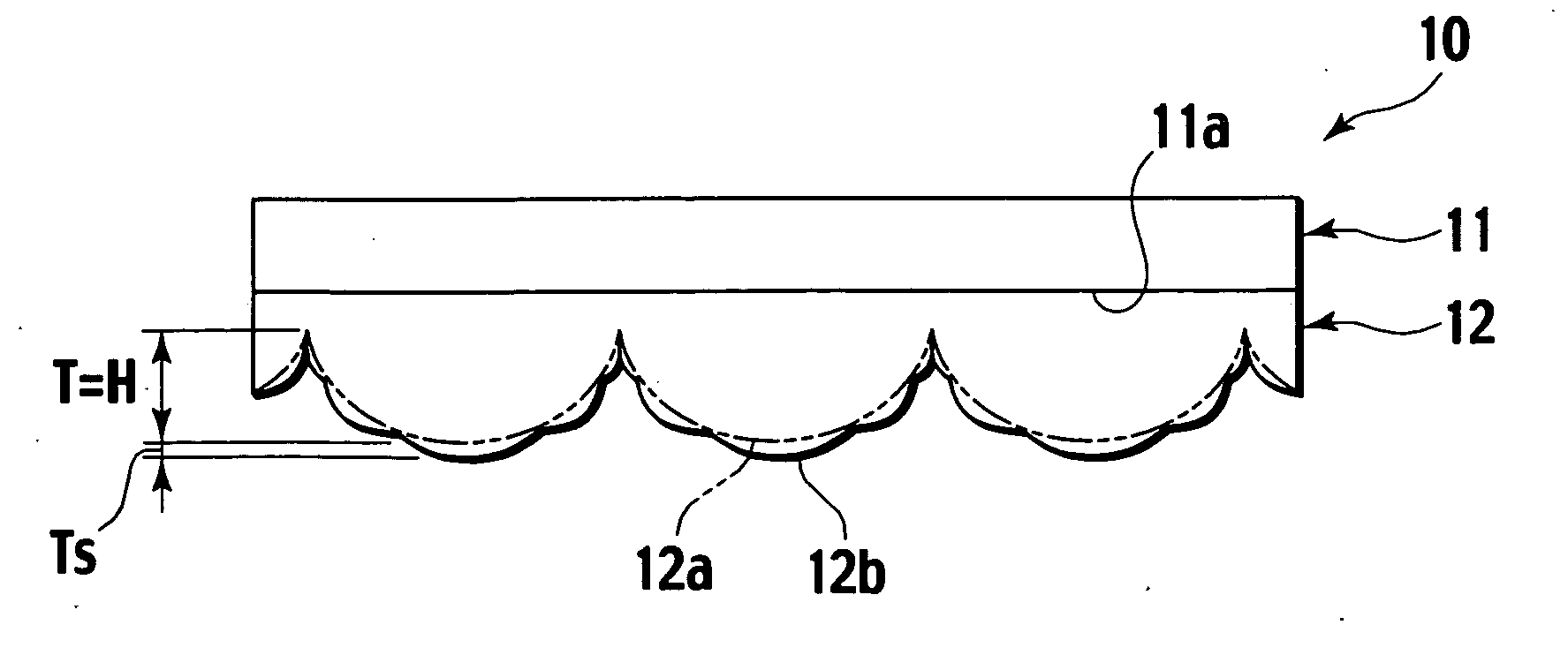
[0052]FIGS. 3A, 3B, and 3C are a front view, a perspective view and a bottom view of a micro lens array according to a first embodiment of the present invention, respectively. FIG. 4 is an explanatory drawing for generally explaining a focal length f of the convex lens having a curvature radius R. FIG. 5 is an enlarged view of one of micro lenses constituting the micro lens array shown in FIGS. 3A to 3C.

[0053] As shown in FIGS. 3A to 3C, a micro lens array 12 according to the first embodiment of the present invention is composed of a lens substrate 11 having an optical transparency and a micro lens array formed integrally on an upper surface 11a of the lens substrate 11. The micro lens array 12 is formed of an optically transparent material and the lens substrate 11 has substantially the same optical transparency as this material.

[0054] More specifically, the lens substrate 11 serving as a base material for a micro lens array element 10 is formed of a resin subst...

example 1

[0121] Firstly, a soda glass substrate 21 having a thickness of 3 mm was prepared as a starting material for a replication mold for a micro lens array. Then, a dry film 22 of 50 micrometer thick was pressed onto the upper surface 21a of the soda glass substrate 21 and heated to be attached thereon.

[0122] Next, a negative mask 23 having alternatively a black portion 23a for blocking light and a transparent portion 23b for allowing light to pass therethrough was placed on the dry film 22. In the negative mask 23, a pitch Px between adjacent two black portions 23a was set, for example, to be 90 micrometers. By the way, a plural of negative masks 23 having the same pitch Px of 90 micrometers and a respectively different width Ax along the X-axis of each black portion 23a were prepared in advance.

[0123] Then, UV-light 24 was exposed to the negative mask 23 from above, thereby forming an unexposed (unhardened) portion 22a at a position in the dry film 22, the position corresponding to e...

example 2

[0132] In Example 2, the micro lens array was manufactured in the same way as Example 1 except that the pitch Px of the openings 22a1 in the dry film 22 was set to be 30 micrometers. The results are listed in FIG. 10B. In FIG. 10B, D is the micro lens bottom face width or the micro lens bottom face diameter as described above, and Dsav is the average sub-lens bottom face width obtained by averaging a plural of the sub-lens bottom face widths Ds or the average sub-lens bottom face diameter obtained by averaging a plural of the sub-lens bottom face diameters Ds.

[0133] From FIG. 10B, it is found that substantially the same result as Example 1 is obtained. In other words, when the width of opening 22a1 in the dry film 22 is changed, the micro lens bottom face width (micro lens bottom face diameter) D remains substantially constant at 130 micrometers for example. This result suggests that any adjacent two micro lens 12a be in a close contact with each other. In addition, the height T (F...


PUM

PropertyMeasurementUnit
Electrical resistanceaaaaaaaaaa
Widthaaaaaaaaaa
Areaaaaaaaaaaa

Abstract

The micro-lens array in which a plural of convexly-protruded micro-lens are closely arranged two-dimensionally and a plural of convex sub-lenses having a curvature-radius smaller than that of the micro-lens are protrusively formed on the surface of each micro-lens has a large view angle, since Dsav/D is in a range from 0.1 to 0.3 where D is the micro-lens bottom face width obtained by halving the summation of the maximum and the minimum width which are measured along the line passing through the center of the bottom face of the micro-lens; Ds is the sub-lens bottom face width obtained by halving the summation of the maximum and the minimum width which are measured along the line passing through the center of the bottom face of the sub-lens; and Dsav is the average sub-lens bottom face width obtained by averaging a plural of the sub-lens bottom face widths Ds.

Description

BACKGROUND OF THE INVENTION [0001] 1. Field of the Invention [0002] This invention relates to a micro lens array in which a plural of a convexly protruded micro lenses are closely arranged in two dimensions and a plural of convex sub-lenses having a smaller curvature radius than that of the micro lenses are protrusively formed along the surface of each micro lens. The present invention also relates to a method of manufacturing a replication mold for the micro lens array. [0003] 2. Description of the Related Art [0004] The micro lens array configured by arranging a plural of convexly protruded micro lenses closely in two dimensions is used for a liquid crystal display, an optical coupler element, an image input device, and the like. [0005] Making use of optical anisotropy, orientation, fluidity and the like of a liquid crystal molecule, a liquid crystal display creates images using a liquid crystal cell on which an optical shutter is arranged the shutter being capable of changing an ...

Claims


Application Information

Patent Timeline
IPC IPC(8): B29C33/38B29C33/42B29D11/00B29L11/00G02B3/00G02B6/32
CPCB29C33/3842B29D11/00278G02B3/0056B29L2011/0016G02B3/0025B29D11/00365
Inventor SUGIYAMA, MASAHIKOSEGAWA, MASARUNAKATANI, YOICHIRO
Owner JVC KENWOOD CORP A CORP OF JAPAN
Why Eureka
Try Eureka