Process for manufacturing reproduction with a luminescence effect and reproduction manufactured by the implementation of the process

a technology of luminescence and manufacturing process, which is applied in the field of manufacturing reproductions with luminescence effects, can solve the problems of limited luminescence characteristics, limited brightness and duration of photoluminescent pigments, and inability to produce reproductions with very high resolution and very sharp images. , to achieve the effect of high quality of detail

Inactive Publication Date: 2005-08-18
PLANCHE PATRICK +2
View PDF12 Cites 1 Cited by
  • Summary
  • Abstract
  • Description
  • Claims
  • Application Information

AI Technical Summary

Benefits of technology

[0010] The object of the present invention is to make it possible to produce, as a reproduction with a luminescence effect, all types of images such as photographic images, technical drawings, artists' works, artificial images, logos, texts, wood-, stone-, metal-, fabric-, liquid-, plant-texture effects, or any other extra effects. These reproductions are produced with a very high quality of detail, of sharpness, of contrast and of colors, while allowing the luminescent image to be very bright and to last longer than that of the current state of the art.
[0013] b. a translucent filter is prepared in order to form a cohesive interface between the luminescent material and a surface provided with an image and to moderate the influence of the color of the luminescent material on the rendition of the reproduction; and
[0015] The advantage of the process according to the invention is that it makes it possible to print any type of image while maintaining its quality, i.e. its shades, its colors and its details, whether the printing is continuous-tone printing, for example laser printing, or positive or negative photographic printing, in order to obtain a photographic quality, or very fine halftone printing, for example offset printing, or full-color area printing, for example screen printing. The condition is that this printing be transparent and produced on one or more surfaces allowing light to pass through them so that the luminescent material can be reached by the light in order to store the light energy optimally, when it is a photoluminescent material, and above all to allow said energy to be regenerated by the light emission from the product through the reproduction and said surfaces. The luminescent material is, of course, preferably photoluminescent, but other materials which may be charged by other forms of energy, such as electrical energy, may be used. If the luminescent product has a color which impairs the quality of the reproduction, a suitable translucent filter must be provided. This filter may either be a film placed over the film with the luminescent product or be incorporated directly into the film with the luminescent material.
[0021] According to another embodiment, the image or parts of the image which are juxtaposed or superposed is / are printed on two different surfaces allowing light to pass through them, thus making it possible to obtain a depth effect and, where appropriate, a relief effect.
[0023] It is also possible to print part of the image, for example the background, on the filter and the other on a transparent carrier, or else to print part of the image on the film comprising the luminescent material and the filter and a transparent carrier. In the latter case, the transparent carrier could also be printed on both faces, completely or partially, thus creating a relief effect in addition to a depth effect. If superposed parts of the image are printed on different surfaces and in different colors depending on the angle of observation, the superposition of the colors will also modify the color of the reproduction.
[0026] According to another variant, the image printed completely or in juxtaposed and / or superposed parts on two different surfaces allowing light to pass through them, thus making it possible to create a depth effect and, where appropriate, a relief effect.

Problems solved by technology

These various processes do not make it possible to produce reproductions having a very high resolution and very sharp images, which may be seen quite faithfully at night as they are during the day.
In addition, the colored photoluminescent pigments offer only a limited number of colors and their luminescence characteristics, both in terms of brightness and in duration, are limited.

Method used


Image

  • Process for manufacturing reproduction with a luminescence effect and reproduction manufactured by the implementation of the process

Examples


Embodiment Construction

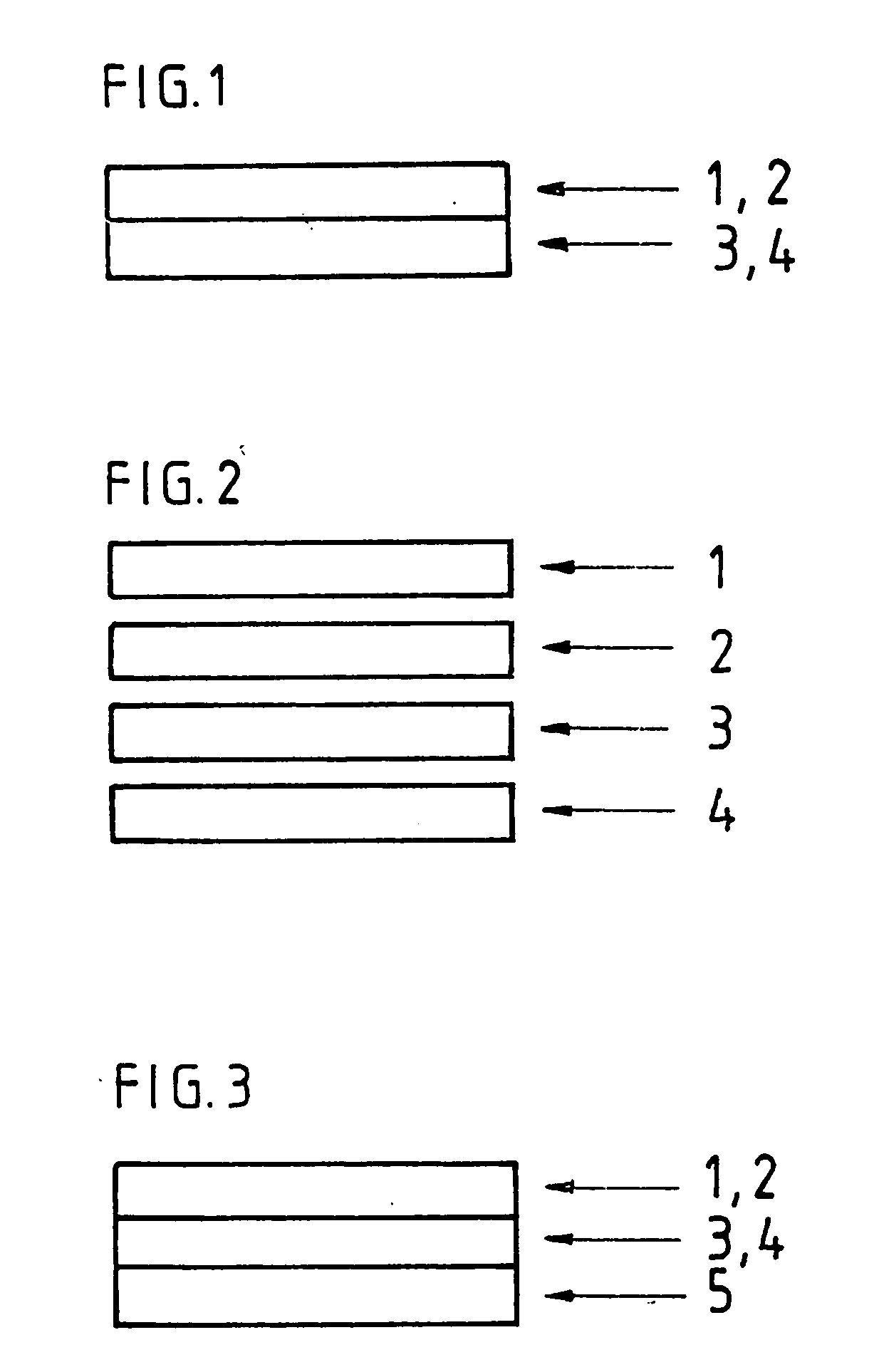
[0032] In the simplest embodiment of the invention, an image 2 is reproduced on a transparent carrier 1 and a film 4 incorporating a luminescent, and more especially a photoluminescent, product is applied to the carrier 1, either on the same side as the printed image or on the other. A filter 3 in the form of a film allowing the effects of the color of the photoluminescent material to be moderated is inserted between the carrier 1 and the film 4.

[0033] More precisely, filter 3 is a translucent material that desaturates the color of the luminescent layer by way of its light scattering capability. Desaturation of color is equivalent to the adding of white to a color thereby making the color less intense. Light which passes through the filter 3 is scattered uniformly thereby giving rise to a white haze, is then reflected off of the luminescent layer 4 and then passes through filter 3 again on its way to the eye of the viewer. Additional scattering of the light occurs during this secon...


PUM

PropertyMeasurementUnit
thicknessaaaaaaaaaa
thicknessaaaaaaaaaa
thicknessaaaaaaaaaa

Abstract

An image is reproduced on a transparent carrier and a film incorporating a photoluminescent product is applied to the carrier, either on the same side as the printed image or on the other. A filter in the form of a film allowing the effects of the color of the photoluminescent material to be moderated is inserted between the carrier and the film. The filter is a translucent material that desaturates the color of the luminescent layer by way of its light scattering capability. Light which passes through the filter is scattered uniformly thereby giving rise to a white haze, is then reflected off of the luminescent layer and then passes through filter again on its way to the eye of the viewer. Different sequences and combinations of the various layers are possible.

Description

[0001] This application is a continuation-in-part of application Ser. No. 08 / 973,592, filed on Apr. 16, 1998BACKGROUND OF THE INVENTION [0002] 1. Field of the Invention [0003] The present invention relates to a process for manufacturing a reproduction with a luminescence effect, and to such a reproduction. [0004] 2. Background of the Invention [0005] It is currently known to make reproductions with a luminescence effect and more specifically a photoluminescence effect of the positive or negative Chinese-shadow image type or images produced using colored photoluminescent pigments. These two types of images having a luminescent effect are essentially produced using the following processes: [0006] by screen printing and optionally offset printing with photoluminescent inks which are colored or not on various carriers, such as paper, fabric, plastic or metal; [0007] by various forms of printing (screen, “pressure-pad”, offset, heat-transfer printing, etc.) on photoluminescent carriers b...

Claims


Application Information

Patent Timeline
Patent Type & Authority Applications(United States)
IPC IPC(8): B41M3/06B44F1/08B44F1/10
CPCB41M3/06B44F1/08Y10T428/24802Y10S428/917Y10T428/25B44F1/10G04B19/10
Inventor PLANCHE, PATRICKPLANCHE, FRANCOISCOLLET, JACQUES-CHARLES
Owner PLANCHE PATRICK
Why Eureka
Try Eureka