Torsional vibration damper

a torsional vibration and damper technology, applied in the design characteristics of springs/dampers, the functional characteristics of springs/dampers, drinking vessels, etc., can solve the problem of primary flywheel oscillation

Inactive Publication Date: 2005-08-18
SCHAEFFLER TECH AG & CO KG
View PDF9 Cites 1 Cited by
  • Summary
  • Abstract
  • Description
  • Claims
  • Application Information

AI Technical Summary

Benefits of technology

[0005] An object of the present invention is to provide a torsional vibration damper which can be installed in the power train of a motor vehicle between the prime mover and the transmission and is constructed and assembled in such a way that any irregularities which develop during operation of the prime mover are isolated (as far as vibratory movements of the output element of the prime mover are concerned) so that they cannot be transmitted to and cannot affect the movements of the secondary flywheel and / or of the part or parts receiving motion from the secondary flywheel.

Problems solved by technology

Furthermore, the nature of operation of the prime mover can be such that, under certain normally undesirable circumstances, the prime mover causes the primary flywheel to oscillate.
Such oscillatory movements of the primary flywheel should not be transmitted to the secondary flywheel because they would be likely to entail damage to the transmission of the power train and / or to generate undesirable noise.

Method used


Image

  • Torsional vibration damper
  • Torsional vibration damper
  • Torsional vibration damper

Examples


Embodiment Construction

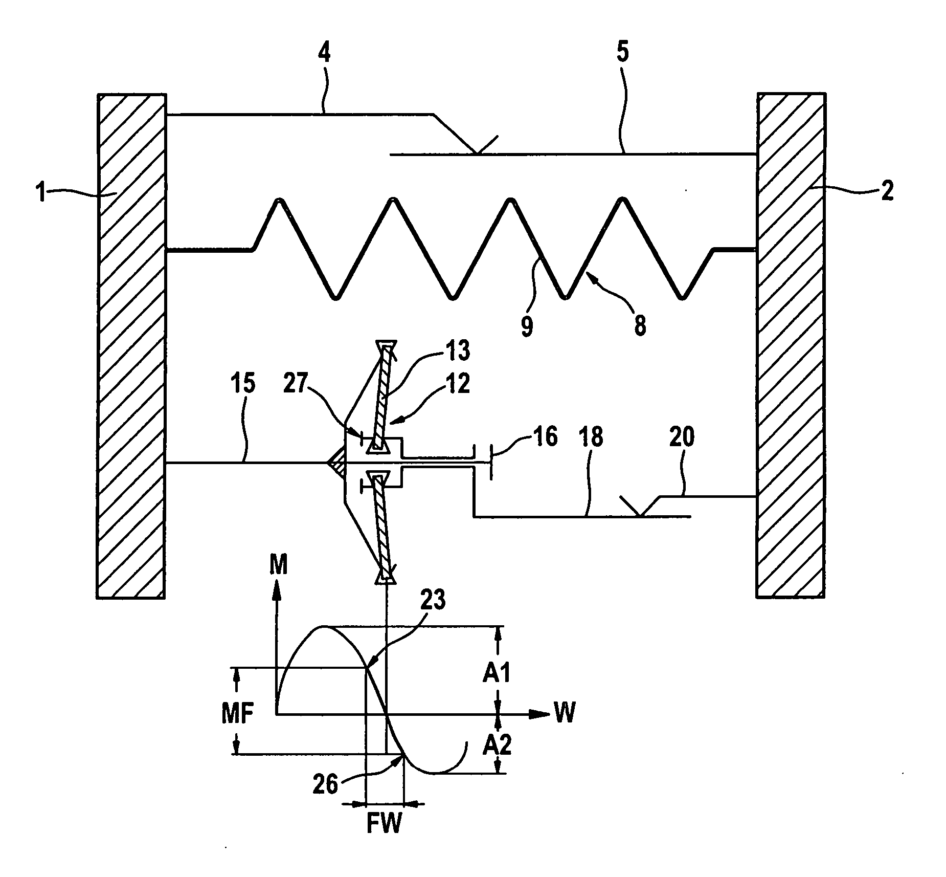
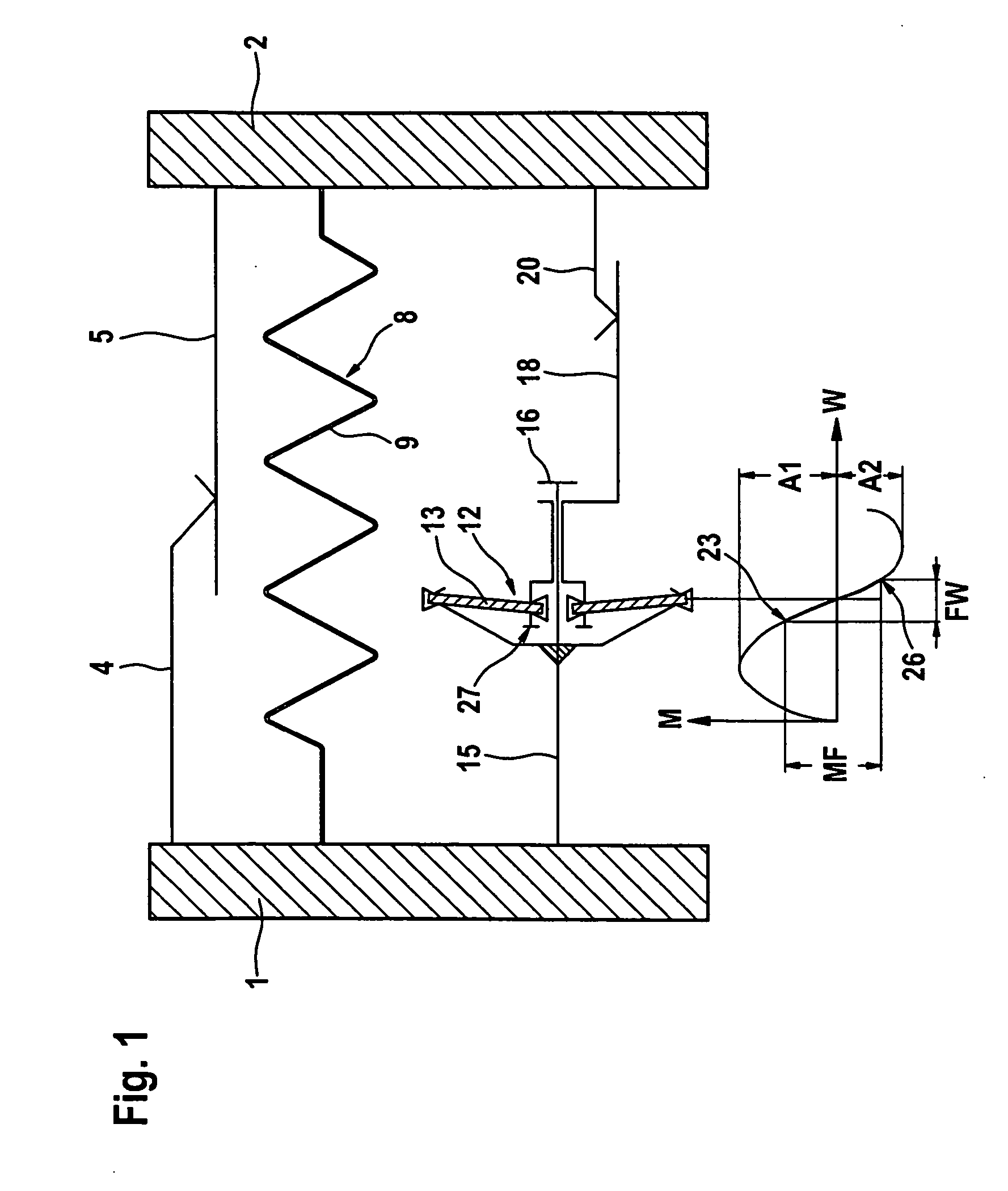
[0026]FIG. 1 illustrates certain relevant component parts of a torsional vibration damper which embodies a first form of the present invention and constitutes a twin-mass flywheel. The latter comprises a first or primary rotary mass or flywheel 1 which is assumed to be affixed to the rotary output shaft (e.g., a crankshaft, not shown) of a prime mover (such as an internal combustion engine) in the power train of a motor vehicle, and a second or secondary rotary mass or flywheel 2. The latter is coaxial with and can rotate relative to the first flywheel 1 and is assumed to be affixed to a rotary input component (e.g., a shaft) of the transmission in the aforementioned power train. A bearing (not shown) is interposed between the flywheels 1 and 2. The basic friction which develops in response to rotation of one of the flywheels 1, 2 relative to the other flywheel is indicated by a first line 4 extending from the first flywheel 1 and having a toothed end portion, an a straight second l...


PUM


Abstract

A torsional vibration damper, particularly for use between the engine and the transmission of the power train in a motor vehicle, including two flywheels rotatable relative to each other against the opposition of a first energy storing device employing, for example, one or more coil springs and a second energy storing device, which is carried by one of the flywheels, which operates in parallel with the first energy storing device and which opposes rotation of the two flywheels relative to each other. In order to isolate the irregularities of movement of the first flywheel (such as vibrations which develop while the engine is in operation) from the second flywheel, the second energy storing device (such as a snap spring or a set of diaphragm springs) is coupled to the flywheels in such a way that the second flywheel develops a degressive action only when the first flywheel is caused to move through relatively small angles (especially between 1° and 10°) but not when the angles are larger (especially larger than 10°).

Description

CROSS-REFERENCE TO RELATED CASES [0001] This-application claims the priority of the commonly-owned copending German patent application Serial No. 10 2004 008 121.2-11 filed Feb. 18, 2004. The disclosure of this German patent application, as well as those of each US and / or foreign patent and / or patent application identified in the specification of the present application, are incorporated herein by reference. BACKGROUND OF THE INVENTION [0002] This invention relates to improvements in torsional vibration dampers, especially to those employing so-called split flywheels, wherein a first or primary rotary flywheel or mass is connectable to the output shaft of a prime mover (for example, the rotary output shaft of an internal combustion engine in the power train of a motor vehicle), a second or secondary rotary flywheel or mass which can be connected to at least one rotary input element of a change-speed transmission in the power train of the vehicle, first energy storing means which ser...

Claims


Application Information

Patent Timeline
Patent Type & Authority Applications(United States)
IPC IPC(8): F16F15/134F16F15/137
CPCF16F15/13469F16F2230/0064F16F15/137F16F2228/12A47G19/23A47J41/0072B65D2581/3478
Inventor FRIEDMANN, OSWALD
Owner SCHAEFFLER TECH AG & CO KG
Why Eureka
Try Eureka