
Thermal improvements for an external combustion engine

a technology of external combustion engine and heater head, which is applied in the direction of machines/engines, hot gas positive displacement engine plants, gas turbine plants, etc., can solve the problems of ineffective heat transfer, inability to use stirling cycle engines in practical applications, and localized overheating of heater tubes and cracked tubes, etc., to prolong the life of the first sheath, improve the thermal contact, and accurate measurement of temperature

Inactive Publication Date: 2005-08-25
NEW POWER CONCEPTS
View PDF99 Cites 13 Cited by
  • Summary
  • Abstract
  • Description
  • Claims
  • Application Information

AI Technical Summary

Benefits of technology

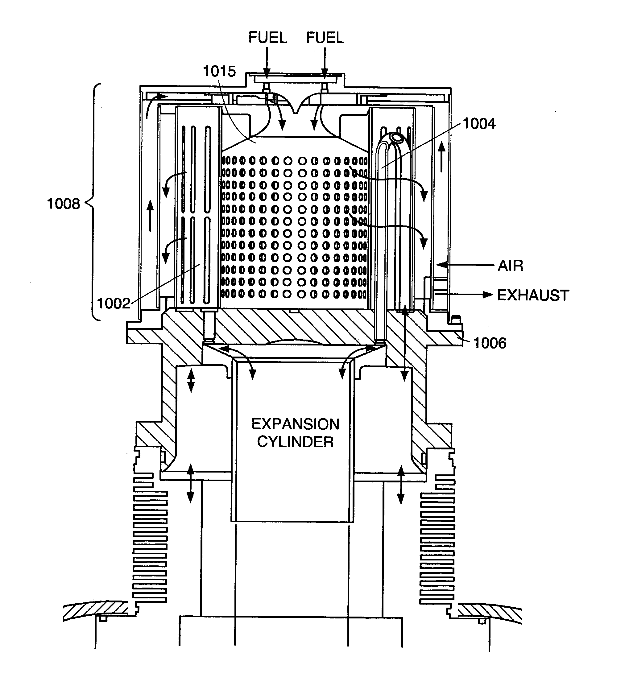
[0014] In accordance with yet another aspect of the invention, there is provided a Stirling cycle engine of the type having a piston undergoing reciprocating linear motion within an expansion cylinder containing a working fluid heated by heat from an external source through a heater head. The Stirling cycle engine has a heat exchanger comprising a plurality of heater tubes in the form of helical coils that are coupled to the heater head. The plurality of helical coiled heater tubes transfer heat from the exhaust gas to the working fluid as the working fluid passes through the heater tubes. In addition, the helical coiled heater tubes are position on the heater head to form a combustion chamber. In one embodiment, each helical coiled heater tube has a helical coiled portion and a straight return portion that is placed on the outside of the helical coiled portion. Alternatively, each helical coiled heater tube has a helical coiled portion and a straight return portion that is placed inside of the helical coiled portion. In another embodiment, each helical coiled heater tube is a double helix. The straight return portion of each helical coiled heater tube may be aligned with a gap between the helical coiled heater tube and an adjacent helical coiled heater tube. In a further embodiment, the Stirling cycle engine includes a heater tube cap placed on top of the plurality of helical coiled heater tubes to prevent a flow of the exhaust gas out of the top of the plurality of helical coiled heater tubes.
[0015] In accordance with another embodiment of the invention, a temperature sensor holder is created by bonding a formed-strip or sheath to the exterior of a heater tube. The sheath is formed such that it makes a channel along the axial portion of a heater tube, when bonded to the tube. A temperature sensor is inserted into this channel to measure the temperature of the heater tube. The sheath allows the sensor to more accurately measure the temperature of the tube rather than the temperature of the combustion gases flowing around the tube. Preferably, the thin strip or sheath is constructed from a refractory or high temperature resistant metal or material. In another embodiment, the sensor holder is a tube which is bonded to the exterior of a heater tube, with a large braze fillet to provide for good thermal contact to the tube. In another embodiment of the invention, a shield is brazed or otherwise bonded to the heater tube substantially covering the sensor holder. The shield insulates the sensor holder from the hot exhaust gases prolonging the life of the first sheath

Problems solved by technology

However, several problems may occur with prior art tube heater head designs such as inefficient heat transfer, localized overheating of the heater tubes and cracked tubes.
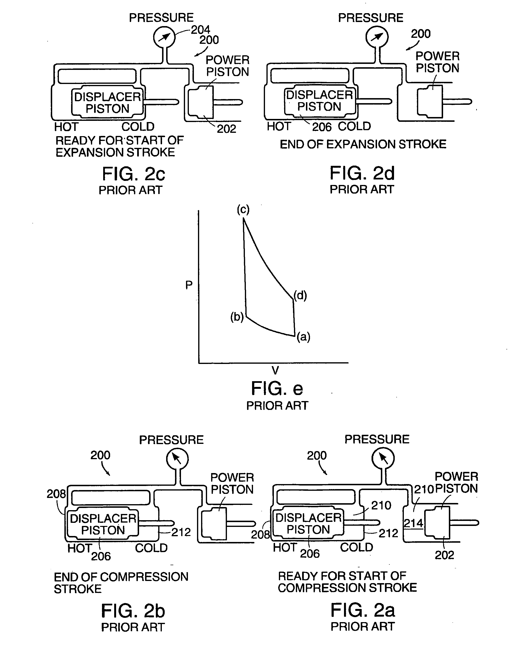
Stirling cycle engines have not generally been used in practical applications due to several daunting challenges to their development.

Method used


Image

  • Thermal improvements for an external combustion engine
  • Thermal improvements for an external combustion engine
  • Thermal improvements for an external combustion engine

Examples


Embodiment Construction

[0042]FIG. 3 is a side view in cross section of a tube heater head and an expansion cylinder. Heater head 306 is substantially a cylinder having one closed end 320 (otherwise referred to as the cylinder head) and an open end 322. Closed end 320 includes a plurality of U-shaped heater tubes 304 that are disposed in a burner 436 (shown in FIG. 4). Each U-shaped tube 304 has an outer portion 316 (otherwise referred to herein as an “outer heater tube”) and an inner portion 318 (otherwise referred to herein as an “inner heater tube”). The heater tubes 304 connect the expansion cylinder 302 to regenerator 310. Expansion cylinder 302 is disposed inside heater head 306 and is also typically supported by the heater head 306. An expansion piston 324 travels along the interior of expansion cylinder 302. As the expansion piston 324 travels toward the closed end 320 of the heater head 306, working fluid within the expansion cylinder 302 is displaced and caused to flow through the heater tubes 30...


PUM


Abstract

An external combustion engine having an exhaust flow diverter for directing the flow of an exhaust gas. The external combustion engine has a heater head having a plurality of heater tubes through which a working fluid is heated by conduction. The exhaust flow diverter is a cylinder disposed around the outside of the plurality of heater tubes and includes a plurality of openings through which the flow of exhaust gas may pas. The exhaust flow diverter directs the exhaust gas past the plurality of heater tubes. The external combustion engine may also include a plurality of flow diverter fins coupled to the plurality of heater tubes to direct the flow of the exhaust gas. The heater tubes may be U-shaped or helical coiled shaped.

Description

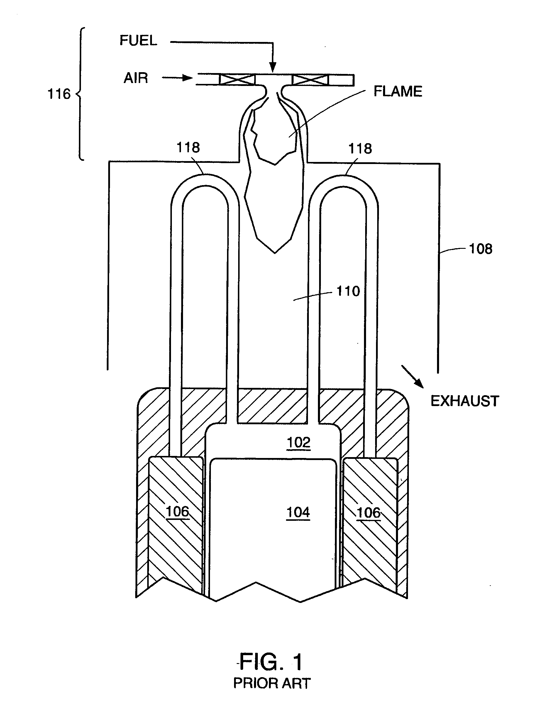
[0001] The present application is a continuation-in-part application of U.S. patent application Ser. No. 10 / 361,354, filed Feb. 10, 2003, attorney docket no. 2229 / 144, now allowed, which is a divisional application of U.S. patent application Ser. No. 09 / 883,077, filed Jun. 15, 2001, which issued as U.S. Pat. No. 6,543,215, each of which is incorporated by reference in its entirety.TECHNICAL FIELD [0002] The present invention pertains to components of an external combustion engine and, more particularly, to thermal improvements relating to the heater head assembly of an external combustion engine, such as a Stirling cycle engine, which contribute to increased engine operating efficiency and lifetime. BACKGROUND OF THE INVENTION [0003] External combustion engines, such as, for example, Stirling cycle engines, have traditionally used tube heater heads to achieve high power. FIG. 1 is a cross-sectional view of an expansion cylinder and tube heater head of an illustrative Stirling cycle ...

Claims


Application Information

Patent Timeline
Patent Type & Authority Applications(United States)
IPC IPC(8): F02G1/043F02G1/055
CPCF02G1/043F02G2255/00F02G1/055
Inventor LAROCQUE, RYAN K.LANGENFELD, CHRISTOPHER C.NORRIS, MICHAEL G.SMITH, STANLEY B. IIISTRIMLING, JONATHAN M.
Owner NEW POWER CONCEPTS
Learn More