Supersonic sensor head for supersonic non-destructive test apparatus

a sensor head and supersonic technology, applied in the direction of instruments, fluid loss/gain rate measurement, fluid tightness measurement, etc., can solve the problems of difficult operation, affecting test accuracy, and difficult to maintain the durability of the free end, so as to facilitate the deformation of the contact medium

Inactive Publication Date: 2005-08-25
SUBARU CORP
View PDF2 Cites 35 Cited by
  • Summary
  • Abstract
  • Description
  • Claims
  • Application Information

AI Technical Summary

Benefits of technology

[0028] It is a sixth object of the invention to provide a supersonic sensor head for a supersonic non-destructive test apparatus by which the non-des...

Problems solved by technology

This operation is not easy.
Therefore, the test accuracy is affected.
Moreover, it is difficult to maintain the durability of the free end 112a of the tube shaped body 112 made of a thin rubber film.
Furthermore, it is not easy to fill the tube shaped body 112 with the liquid ...

Method used


Image

  • Supersonic sensor head for supersonic non-destructive test apparatus
  • Supersonic sensor head for supersonic non-destructive test apparatus
  • Supersonic sensor head for supersonic non-destructive test apparatus

Examples


first embodiment

(First Embodiment)

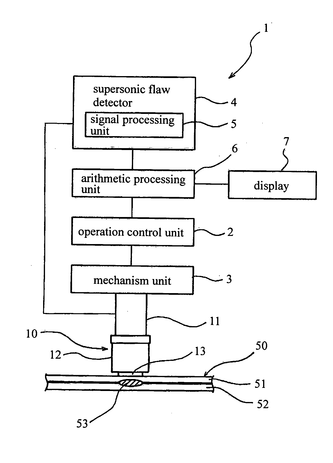
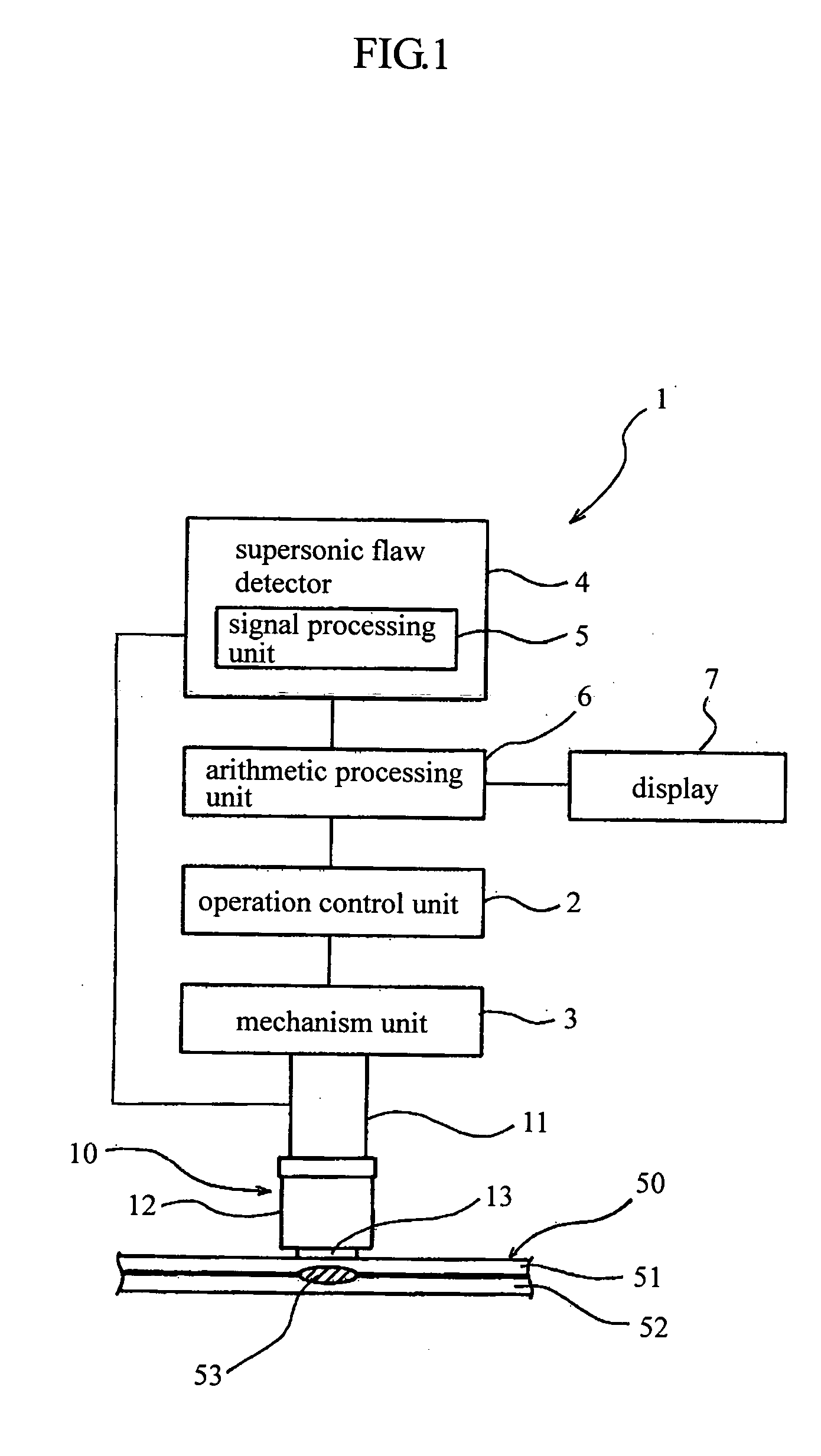
[0041] A first embodiment of a supersonic sensor head for a supersonic non-detective test apparatus according to the present invention will be explained by referring to FIGS. 1 and 2. FIG. 1 is a schematic diagram for explaining a supersonic non-destructive test apparatus 1, and FIG. 2 is a cross section for showing the supersonic sensor head in FIG. 1.

[0042] In the supersonic non-destructive test apparatus 1, a sensor head 10 with a supersonic vibrator 11 causes a mechanism unit 3 to move based on a control signal transmitted from an operation control unit 2. Then, the supersonic sensor head 10 is pressed against a surface of a test object 50. In this state, a supersonic wave is transmitted from a supersonic flaw detector 4 to a supersonic vibrator 11 of the supersonic sensor head 10 through a signal treatment unit 5 in the supersonic flaw detector 4 and an arithmetic processing unit 6. The supersonic wave is output from the vibrator 11 to the test object 50 and ...

second embodiment

(Second Embodiment)

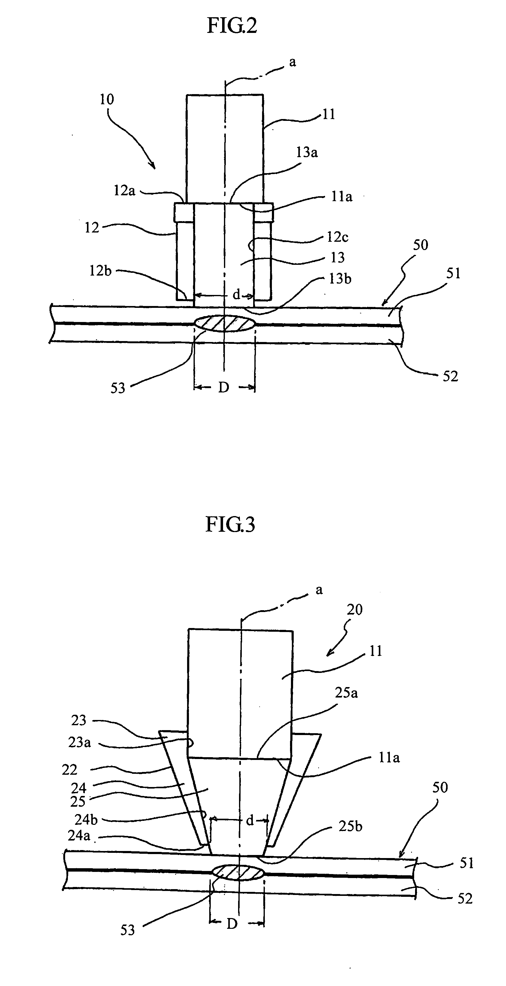
[0055]FIG. 3 is a schematic cross section for explaining a supersonic sensor head as a second embodiment. Structural parts in FIG. 3 corresponding to those in FIG. 2 are shown with the same reference numerals in both the figures, and the explanation on the corresponding parts will be omitted.

[0056] A supersonic sensor head 20 in the second embodiment is in the form of a column having a flat free end 11a, as in the first embodiment. A holder 22 is provided coaxially with a supersonic vibrator 11 with being connected to the free end 11a of the supersonic vibrator 11. The holder 22 is detachably connected to the outer periphery of the supersonic vibrator 11 at a lower position thereof. The holder 22 contains a contact medium 25 therein, similar to the first embodiment. The contact medium 25 is also made of a gel material such as a silicone rubber. The holder 22 is made of a material which makes it difficult for a supersonic wave to be transmitted therethrough. The h...

third embodiment

(Third Embodiment)

[0062]FIGS. 4A and 4B are schematic diagrams for explaining the supersonic sensor head as a third embodiment of the present invention. FIG. 4A is a cross section of the supersonic sensor head, and FIG. 4B is a diagram of the supersonic sensor head obtained by viewing FIG. 4A in the direction of an arrow A in FIG. 4A. Structural parts in FIG. 4 corresponding to those in FIGS. 2 and 3 are shown with the same reference numerals therein and the explanation on the corresponding parts will be omitted.

[0063] A supersonic sensor head 30 in the third embodiment is in the form of a column having a flat free end 11a as in the first embodiment. A holder 32 with a converging mechanism 35 is provided coaxially with the supersonic vibrator 11 with respect to an axis a, by being connected to the free end 11a of the supersonic vibrator 11. The holder 32 contains a contact medium 40 therein, similar to the first embodiment. The contact medium 40 is also made from a gel material suc...


PUM


Abstract

A supersonic sensor head for a supersonic non-destructive test apparatus is disclosed. The supersonic sensor head includes a supersonic vibrator for transmitting and receiving supersonic waves, a holder having a base end and an opening end, and a soft gel material contact medium provided in the holder between the vibrator and a test object. The holder is coaxial with the vibrator so that the base end of the holder is in contact with a free end of the vibrator. By way of the contact medium, the supersonic vibrator indirectly contacts the test object. When a contact part of the contact medium is pressed against the test object, the vibrator comes into close contact with the contact medium, and the contact medium comes into close contact with the test object. The opening end of the holder restricts the deformation of the contact part of the contact medium.

Description

CROSS REFERENCE TO RELATED APPLICATIONS AND INCORPORATION BY REFERENCE [0001] This application is based upon and claims the benefit of priority from the prior Japanese Patent Application No. 2004-049407, filed on Feb. 25, 2004; the entire content of which is incorporated herein by reference. BACKGROUND OF THE INVENTION [0002] 1. Field of the Invention [0003] The present invention relates to a supersonic sensor head for a supersonic a non-destructive test apparatus for examining a test object without destroying the same. [0004] 2. Discussion of the Related Art [0005] In a method for manufacturing articles such as machines and structures, plates manufactured by deformation processing are welded to each other. The stability of the welded parts is sometimes confirmed by the non-destructive test when the welded structures are required to have a particularly high reliability. [0006] As an apparatus for the non-destructive test, a supersonic non-destructive test apparatus is known. When th...

Claims


Application Information

Patent Timeline
IPC IPC(8): G01N29/04G01N29/07G01N29/24G01N29/28
CPCG01N29/07G01N2291/2672G01N2291/101G01N29/28
Inventor KAWABATA, SHINYA
Owner SUBARU CORP
Why Eureka
Try Eureka