

Pilot operated relief valve
a relief valve and pilot technology, applied in the field of relief valves, can solve the problems of insufficient hydraulic system pressure to perform the operation, inconvenient user change the setting pressure, and temporary increase of the setting pressure of the pilot operated relief valv
- Summary
- Abstract
- Description
- Claims
- Application Information
AI Technical Summary
Benefits of technology
Problems solved by technology
Method used
Image

Examples
Embodiment Construction
[0048] A preferred embodiment of the present invention will now be described with reference to the accompanying drawings. In the following description, same drawing reference numerals are used for the same elements even in different drawings. The matters defined in the description such as a detailed construction and elements of a circuit are nothing but the ones provided to assist in a comprehensive understanding of the invention. Thus, it is apparent that the present invention can be carried out without those defined matters. Also, well-known functions or constructions are not described in detail since they would obscure the invention in unnecessary detail.
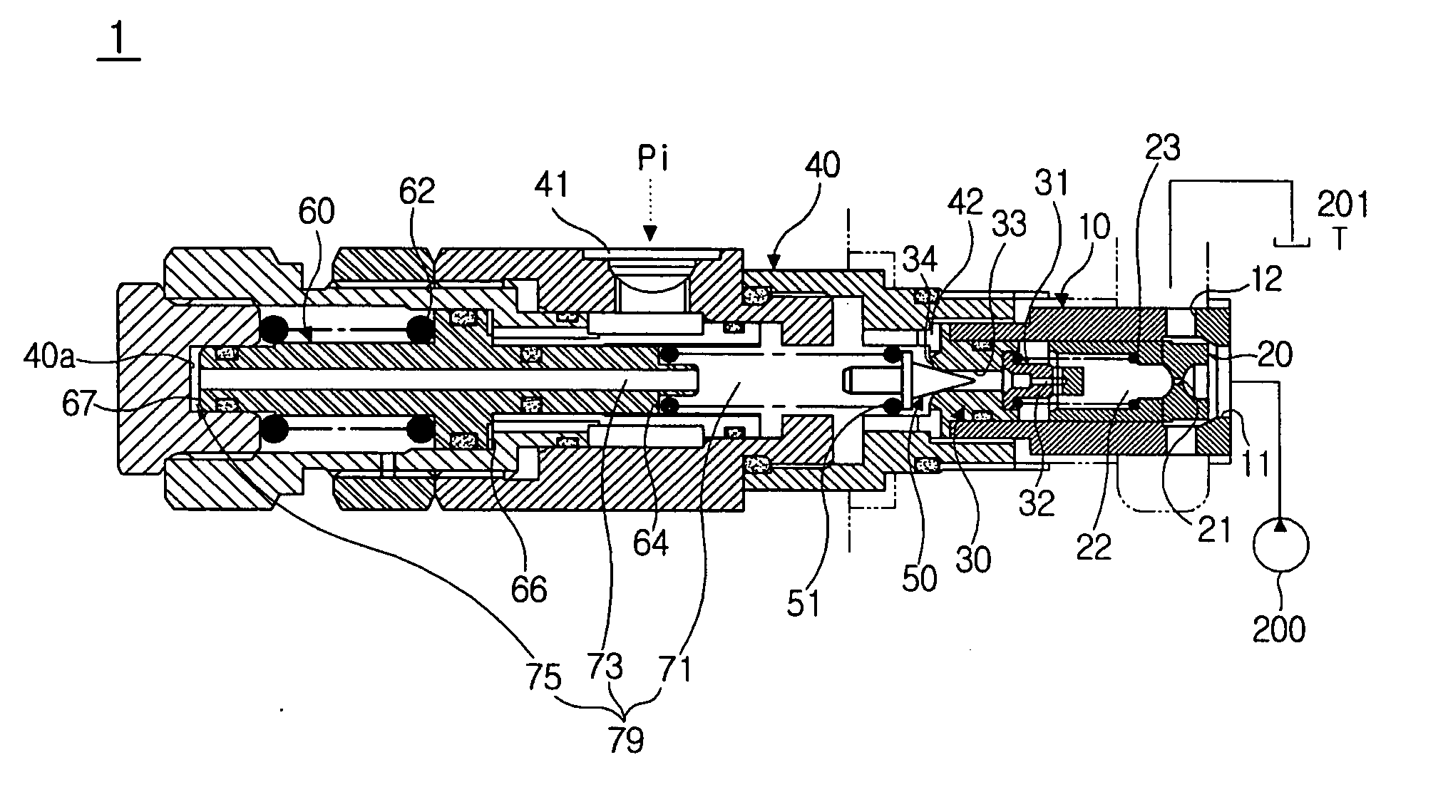
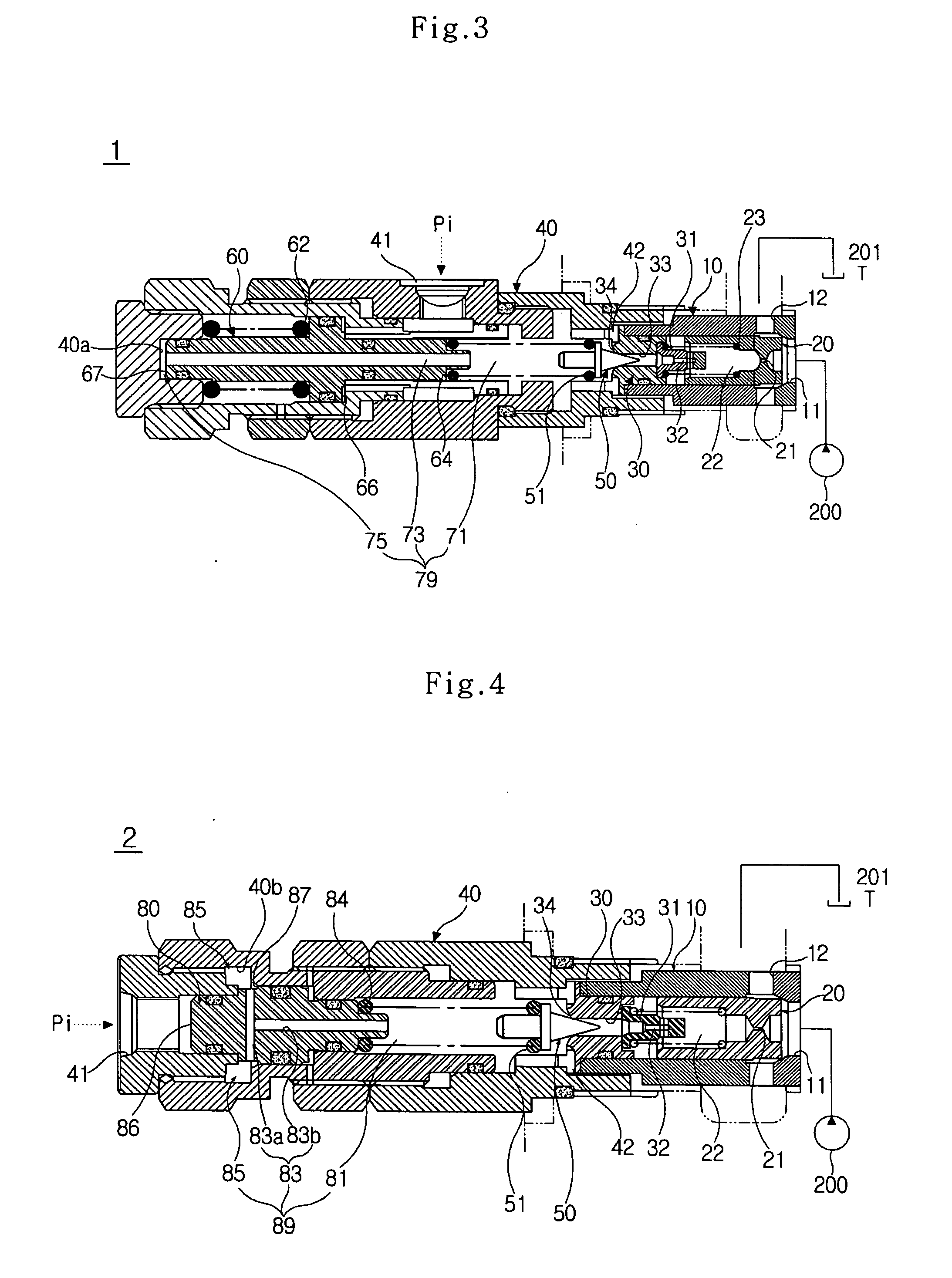
[0049]FIG. 3 is a cross-sectional view of a pilot operated relief valve 1 according to a first embodiment of the present invention.
[0050] The relief valve 1 is comprised of a sleeve 10, a main poppet 20 movably mounted on the sleeve 10, a seat 30 mounted on the sleeve 10, a housing 40 connected to a rear end of the sleeve 10, a...
PUM
 Abstract
Description
Claims
Application Information