Electric power tool

Inactive Publication Date: 2005-08-25
RYOBI
View PDF7 Cites 32 Cited by
  • Summary
  • Abstract
  • Description
  • Claims
  • Application Information

AI Technical Summary

Benefits of technology

[0013] An object of the present invention is therefore to provide an electri

Problems solved by technology

However, the former conventional impact driver has the bosses projecting outward so as to hinder an operator from carrying out a working operation at a corner or narrow portion to be worked or to damage a material made for example of wood into which screws are to be inserted.
In addition, the latter conventional impact driver involves the following problems: (1) The hammer case is connected indire

Method used


Image

  • Electric power tool
  • Electric power tool
  • Electric power tool

Examples


Embodiment Construction

[0030] Now, embodiments of an electric power tool of the present invention will be described in detail below with reference to the accompanying drawings.

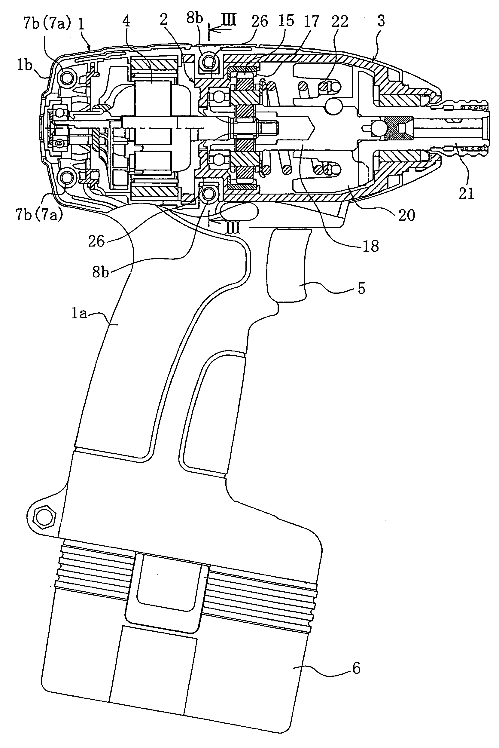
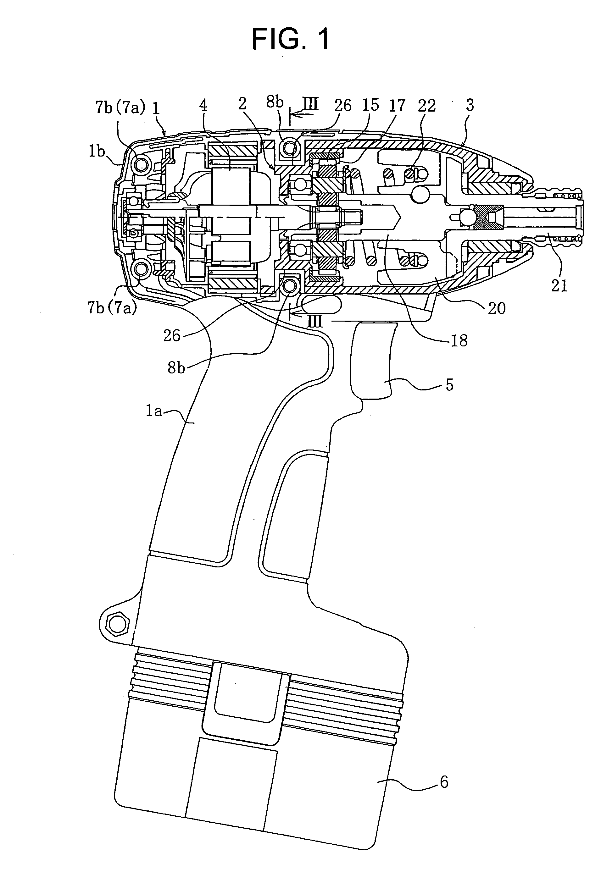
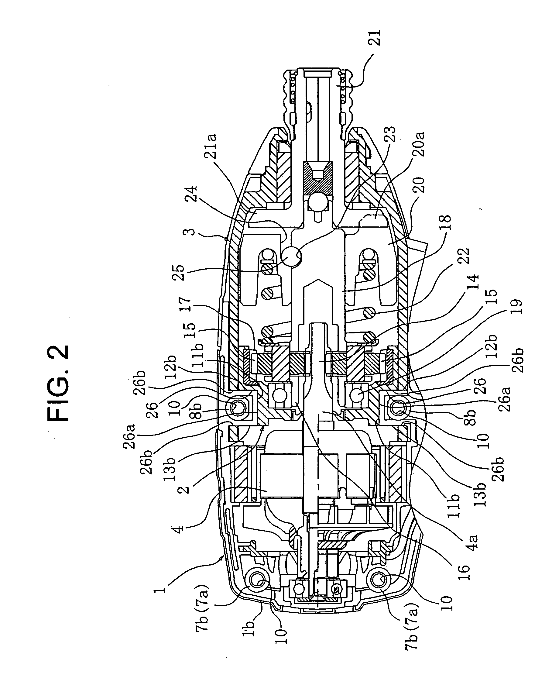
[0031] As shown in FIGS. 1 to 4, the electric power tool of the present invention is constructed as an impact driver. The impact driver has a fundamental structure including a housing 1 for forming an outer shell, an inner case 2 and a hammer case 3.

[0032] The housing 1 is divided into a pair of right-hand and left-hand half portions 1a, 1b that are to be assembled into a united body. The housing 1 has an upper side in which a motor 4 and the other structural components are received, and a lower side that serves as a handle. The motor 4 has a drive shaft 4a, which is placed on the central axial line of the upper side of the housing 1. The drive shaft 4a projects forward, i.e., toward the hammer case 3 and the inner case 2. A boundary zone between the upper and lower sides of the housing 1 receives a switch box (not shown) in which...


PUM


Abstract

An electric power tool includes a housing, an inner case and a hammer case. The housing receiving a motor has a pair of half portions. The inner case receives a planetary gear train. An input side of the planetary gear train is connected to a drive shaft of the motor. The housing receives the inner case. The hammer case receives a hammer unit. An input side of the hammer unit is connected to an output shaft of the planetary gear train to convert rotation of the output shaft of the planetary gear train into an intermittent striking power outputted from an output shaft of the hammer unit. The hammer case receives the inner case having recesses. The hammer case has elongated holes aligned with the recesses. Each half portion has bosses engaging with the elongated holes of the hammer case, which are aligned with the recesses of the inner case.

Description

BACKGROUND OF THE INVENTION [0001] 1. Field of the Invention [0002] The present invention relates to an electric power tool such as an impact driver. [0003] 2. Related Art [0004] An impact driver includes a housing, a hammer case received in the housing, and an inner case received in the hammer case. The housing accommodates not only the hammer case and the inner case, but also a motor having a drive shaft, a switch and the other structural components. The inner case accommodates a planetary gear train having an input side and an outputs shaft, which is connected to the drive shaft of the motor to transmit power of the motor to the output shaft at reduced speed. The hammer case accommodates a hammer unit having an input side and an output shaft. The input side of the hammer unit is connected to the output shaft of the planetary gear train to convert rotational motion of the output shaft of the planetary gear train into an intermittent striking power outputted from the output shaft o...

Claims


Application Information

Patent Timeline
IPC IPC(8): B25F5/02B25B21/02B25D9/00
CPCB25B21/02
Inventor WADA, YASUOMORIMUNE, SHINJI
Owner RYOBI
Why Eureka
Try Eureka