Storm water treatment apparatus employing dual vortex separators

a treatment system and vortex separator technology, applied in separation processes, liquid displacement, filtration separation, etc., can solve the problems of heightened burden on those who regularly maintain these systems, easy access and maintenance, and high installation and maintenance costs, and achieve high flow capability, easy maintenance, and high flow

Active Publication Date: 2005-08-25
OLDCASTLE PRECAST
View PDF4 Cites 51 Cited by
  • Summary
  • Abstract
  • Description
  • Claims
  • Application Information

AI Technical Summary

Benefits of technology

[0011] The present invention generally relates to a novel, in-line hydrodynamic filtration system for stormwater runoff in which dual vortex separators are used to remove sediments from runoff. The separators are designed to function in stages, to treat the lowest flows in one separator, with diversion of increasing flows to a second separator. At peak flow, an in-line bypass allows such excess flow to pass through the filtration system, thereby preventing backup of stormwater, while at the same time leaving accumulated materials undisturbed.
[0014] In most cases, the flows are directed to either the first or second separator for treatment. When flows from storm runoff increase beyond the capacity of the two separators, water will flow over the second weir, thereby continuing through the assembly to exit into the storm drain system for later discharge or treatment. It is preferred that the capacity of the pass-through member be equal to or larger than that of the drainage pipe supplying the system, to prevent the possibility of backup. Having such an inline, high flow capability, the need for a secondary unit, or placement of the unit offline, to accommodate a condition of high flow is eliminated.
[0015] As important as treatment capability is, it is also vital that treatment units be easily maintainable, and provide access to allow for complete cleanout. In the embodiment wherein the pass-through member comprises a closed wall through-pipe, the through-pipe is provided with an opening at its top to permit access to the weirs disposed there-within. Such allows for visual inspection of weirs and access for necessary cleanout to assure debris, which could block flow to either of the vortex separators, or over the second weir to outfall the unit, is not allowed to accumulate. In the embodiment where the pass-through member comprises an open-top bypass chute, inherent in this design is the providing of full access to the weir structures for easy inspection and cleanout. As a further feature of either embodiment, the treatment unit can be provided as an integrated assembly which can be easily disconnected from the walls of the basin into which it has been secured, and sized to be completely removed from the manhole via the manhole cover, thus allowing full access to all areas of the basin for cleaning and removal of accumulated sludge and debris.

Problems solved by technology

However, these systems are also generally permanent installations that are expensive to install and maintain.
Moreover, because such filtration systems typically require regular maintenance, issues arise such as ease of access and the length of time that a system can operate between cleaning or replacing filter elements or other parts.
Access to elements that must be cleaned or replaced is problematic in some systems, such that a heightened burden is placed on those who regularly maintain these systems.
Another significant problem that has emerged in the development of catch basin filtration systems is the ability of such systems to process large quantities of fluid during peak flow periods without having backups or stoppages that result in localized flooding of surrounding areas.
As a result, these types of filtration systems have an upper limit as to the amount of fluid that can be filtered at any given time as well as a maximum capacity for the amount of fluid that can be passed through the system in any event.
However, the units currently available require custom installation, and like the inlet catch basin filtration systems earlier described, require periodic maintenance to remove accumulated sludge and debris.
Because of the configuration and lack of portability of these units, they do not allow for easy cleaning of the manhole into which they have been placed.

Method used


Image

  • Storm water treatment apparatus employing dual vortex separators
  • Storm water treatment apparatus employing dual vortex separators
  • Storm water treatment apparatus employing dual vortex separators

Examples


Embodiment Construction

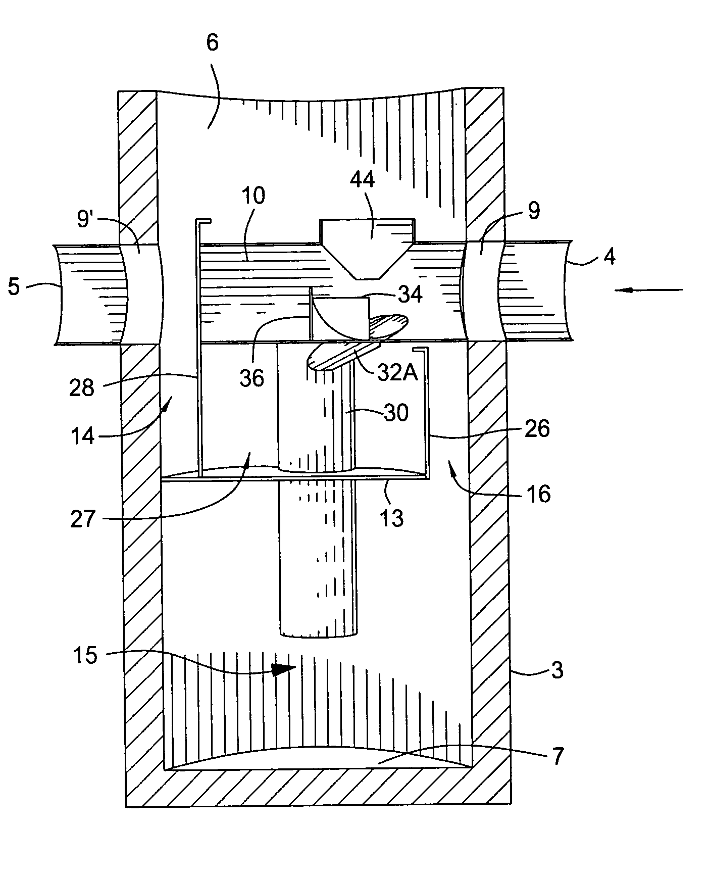
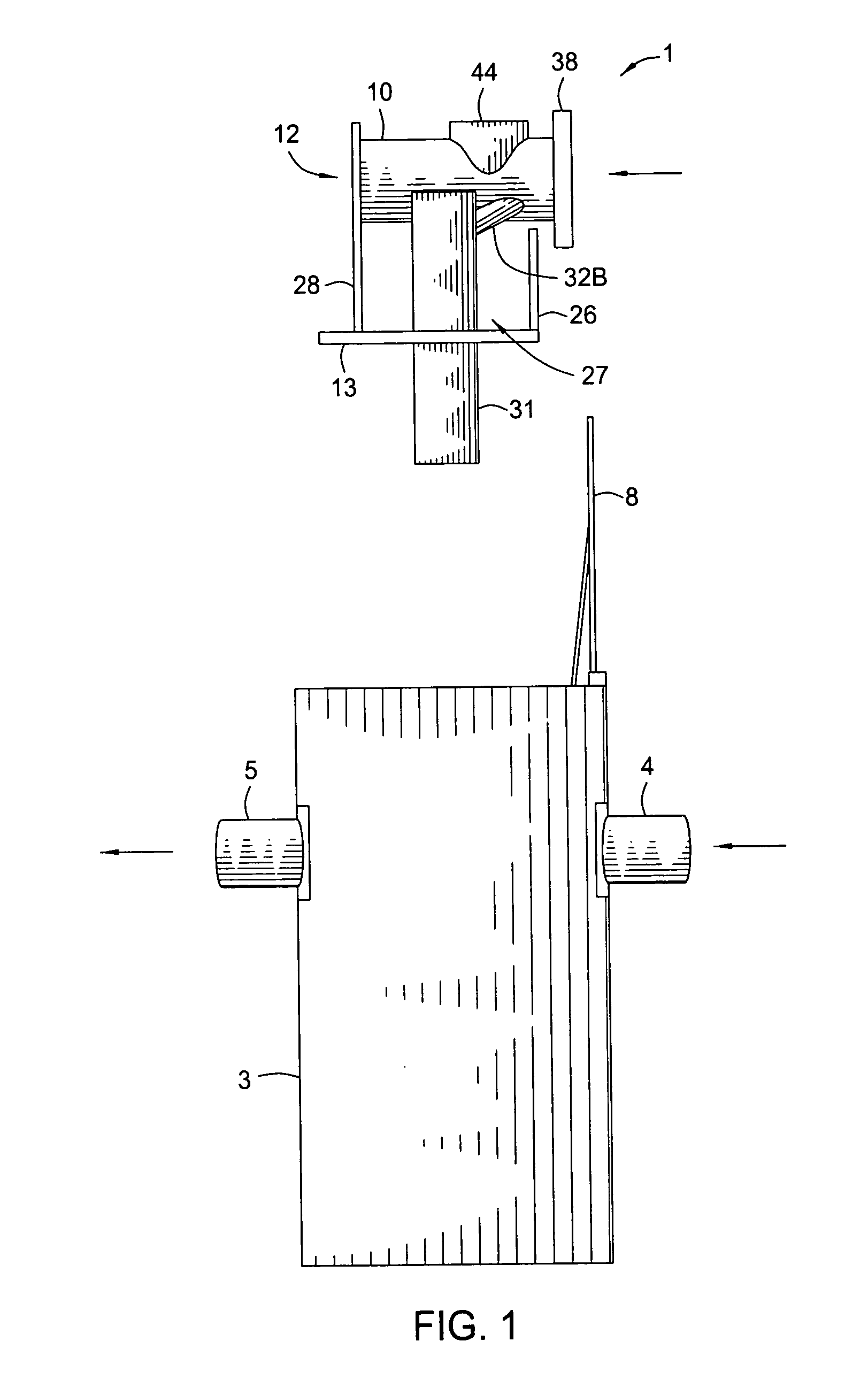
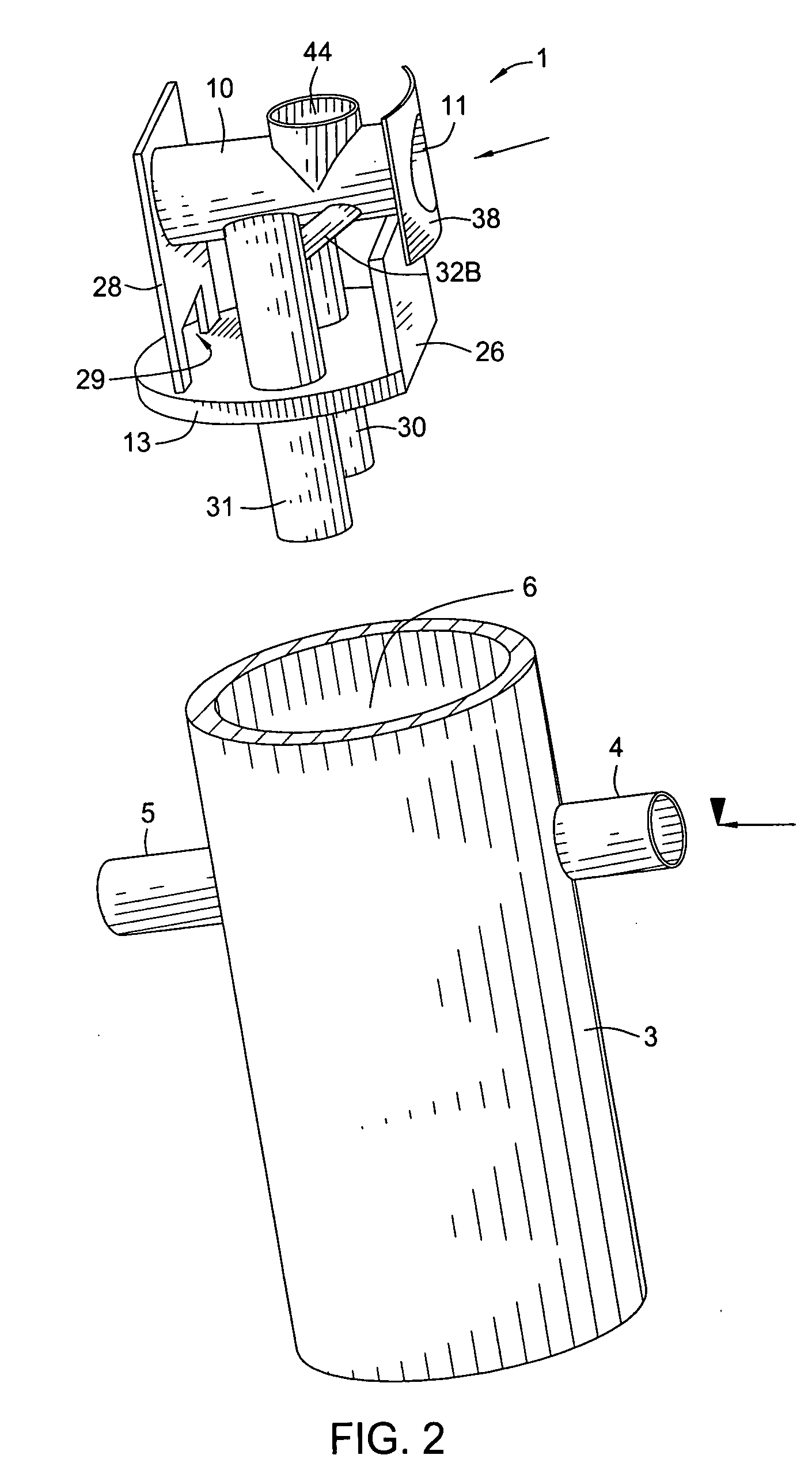
[0027] The separator assembly of the present invention will now first be described with reference to the embodiment of FIGS. 1 through 4. The separator assembly 1 is shown in position above a manhole basin 3, connected to an inlet pipe 4 and an outlet pipe 5. The manhole basin is typically cylindrical in shape, having a smooth inner wall 6, a bottom floor 7, and a top, which is provided with an openable manhole cover 8, for allowing access to the basin. Inlet opening 9 is sized to receive a drain pipe carrying stormwater from one of more drains. The inlet is usually spaced at least one full equivalent manhole diameter distant from base 7 of the manhole. Typically, for the 4 foot diameter manhole illustrated in the figures, the inlet pipe will have a maximum diameter of 12 inches. For standard 5 and 6 foot diameter manholes, the inlet pipes are sized to a maximum of 18″ and 24″, respectively. Outlet opening 9′ in the wall of the manhole is positioned opposite to and somewhat below in...


PUM

PropertyMeasurementUnit
diameteraaaaaaaaaa
diameteraaaaaaaaaa
sizeaaaaaaaaaa

Abstract

A stormwater treatment device for removing floatables, solids and suspended particles and the like from stormwater run off, whereby a removable assembly is provided for installation into a manhole basin, the assembly including a pass-through member which receives stormwater from an incoming drainage system, and diverts low flows to at least one or more vortex separators, while allowing for high flows to bypass the separators and flow through the assembly untreated to exit the basin without diversion.

Description

[0001] This application claims benefit of Provisional Patent Application Ser. No. 60 / 546,623 filed Feb. 20, 2004 and Provisional Patent Application Ser. No. 60 / 614,598 filed Sep. 29, 2004, both of which applications are incorporated herein by reference.BACKGROUND OF THE INVENTION [0002] 1. Field of the Invention [0003] Embodiments of the present invention generally relate to methods and apparatus for treatment of stormwater runoff, and more particularly to a stormwater treatment system employing dual vortex separators for removing debris and suspended particles from such stormwater runoff. [0004] 2. Description of the Related Art [0005] Drainage systems for receiving fluid flow are well known in the art. Such systems provide a path for fluid flow from surface areas and often transport the fluid from surface areas directly to the ocean, rivers, lakes, estuaries, streams and the like without regard to the removal of debris, pollutants or other contaminants. For example, because of the...

Claims


Application Information

Patent Timeline
Patent Type & Authority Applications(United States)
IPC IPC(8): C02F1/00C02F1/38E03F5/14
CPCC02F1/38E03F5/14C02F2301/043C02F2103/001
Inventor ALLARD, DOUGLAS PAULMCDONALD, JONATHAN
Owner OLDCASTLE PRECAST
Why Eureka
Try Eureka